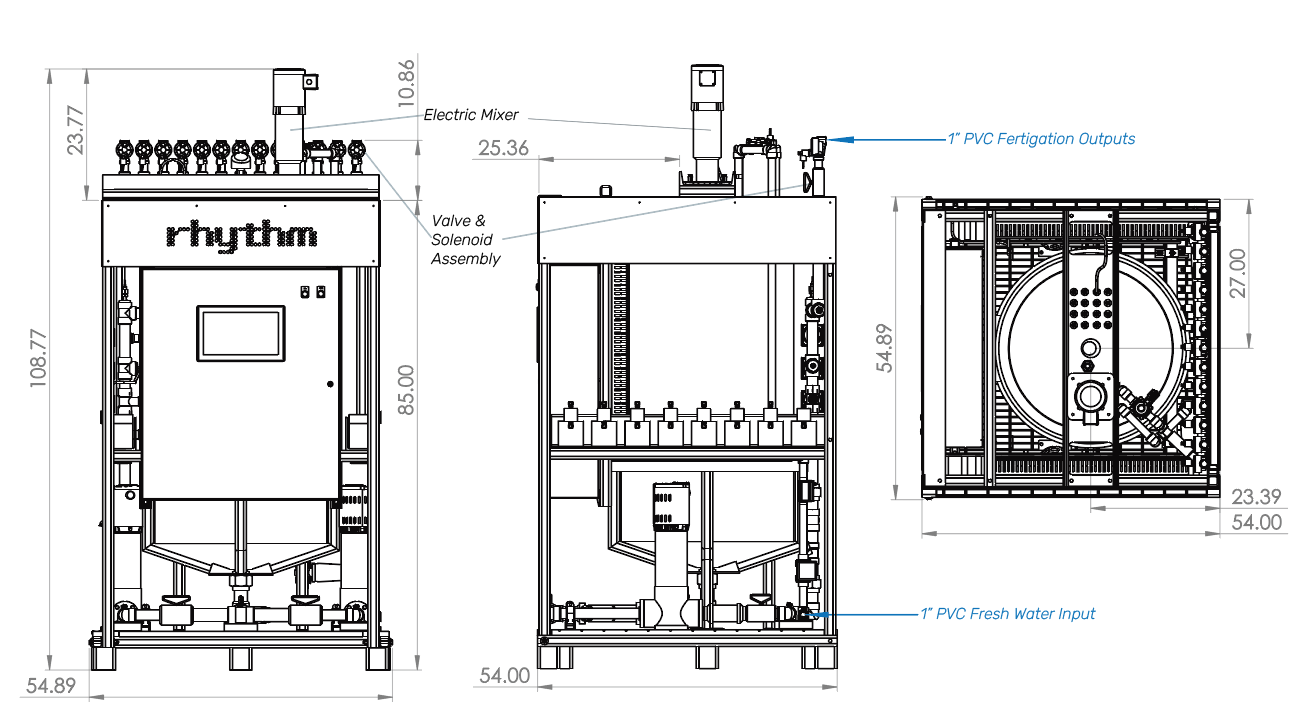
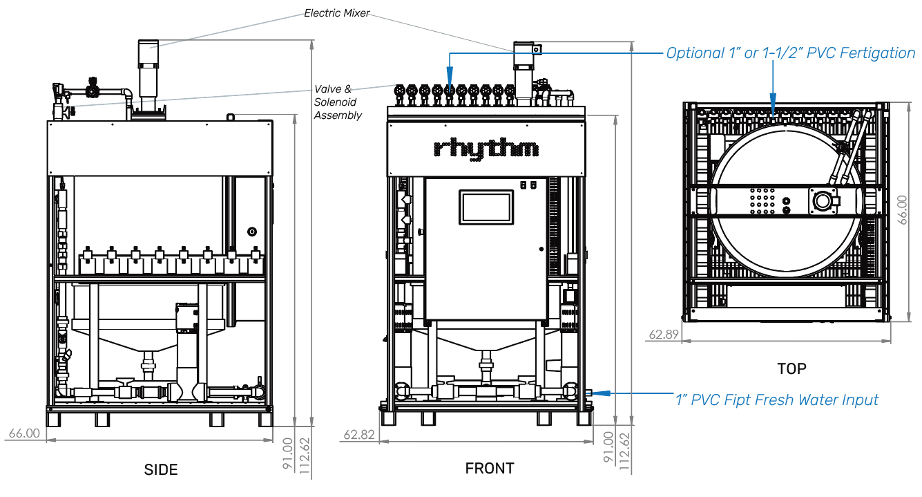
The Batch Series AFS was designed to be compact and require as little physical space as possible. See below for specific space requirements and recommended clearances. The overall height of the Batch Series AFS is substantially taller with the electric mixer installed. The mixer and shaft come disassembled and temporarily bound to the AFS frame for shipping.
DO NOT INSTALL THE ELECTRIC MIXER UNTIL MACHINE IS SET INTHE FINAL RESTING SPOT.
A forklift or a pallet jack may be used to maneuver the equipment into place. Ensure there is a viable path prior to moving the AFS to the desired location. Follow all required electrical and building codes for minimum clearances needed.
Notes
Please allow 18" minimum between the back of the machine and the wall it backs.
Please allow a good cushion of size around the calibration sensors for routine calibration, maintenance, and replacing duties.
Please allow 38" of space in front of the machine to allow the control cabinet door to safely open.
AFS-B350 - 350 Gallon Single Batch Series
Notes
Please allow 24" minimum between the back of the machine and the wall it backs.
Please allow a good cushion of size around the calibration sensors for routine calibration, maintenance, and replacing duties.
Please allow 38" of space in front of the machine to allow the control cabinet door to safely open.
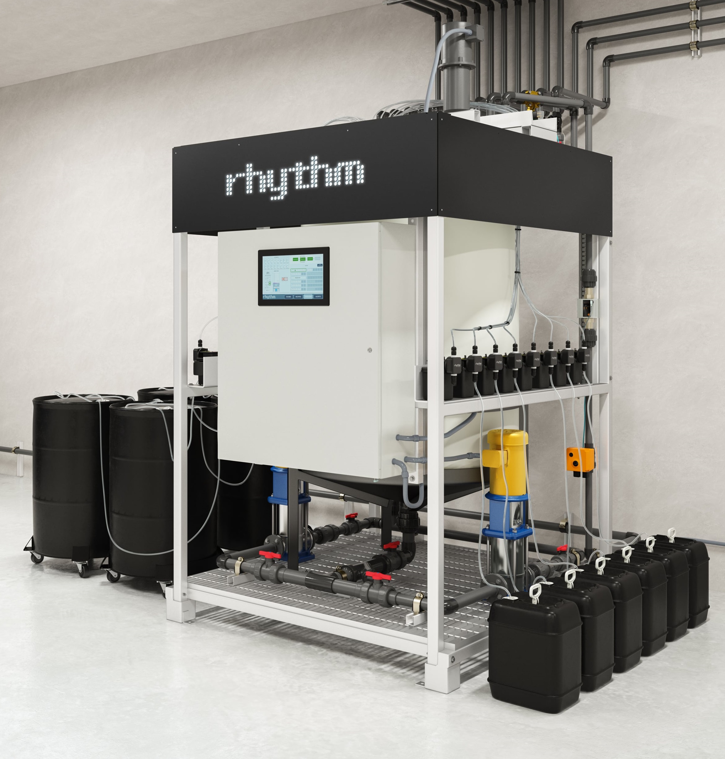
Example of nutrient placement for Single Batch systems
Rhythm includes 10ft of tubing per dosing pump. Replacement or supplementary tubing can be purchased at any home improvement store, the sizing would be 1/4" ID (inner diameter) x 3/8" OD (outer diameter).
Nutrient containers can be placed above, horizontal to, or below dosing pumps. Please note, the pumps are rated for 10ft of suction lift.
Notes
The wall behind the Multi-Batch is where the (Rhythm provided) plumbing manifold mounts. The space between this wall and the back of the machine must be 30-36".
Please allow 38" of space in front of the machine to allow the control cabinet door to safely open.
Dosing panels vary per customer. Your project may have 1 or 2 panels and they come in the following sizes: 12 pump, 16 pump, and 20 pump options.
Example of nutrient placement for Multi Batch systems
Rhythm includes 10ft of tubing per dosing pump. Replacement or supplementary tubing can be purchased at any home improvement store, the sizing would be 1/4" ID (inner diameter) x 3/8" OD (outer diameter).
Nutrient containers can be placed above, horizontal to, or below dosing pumps. Please note, the pumps are rated for 10ft of suction lift.
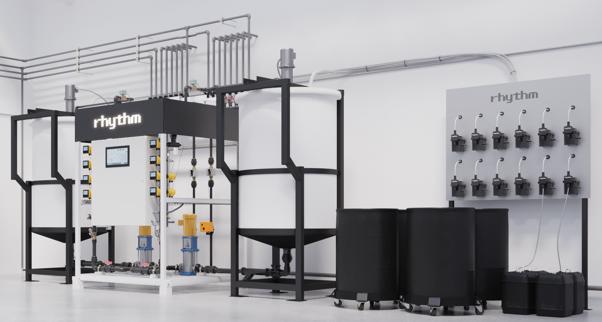
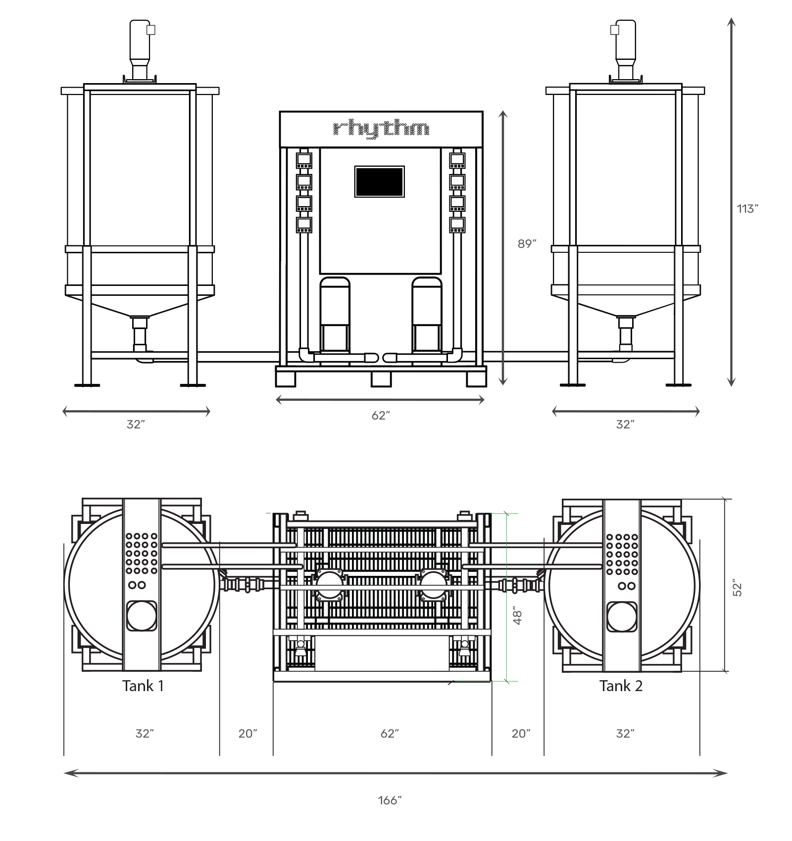
TS-200 (Gallon)
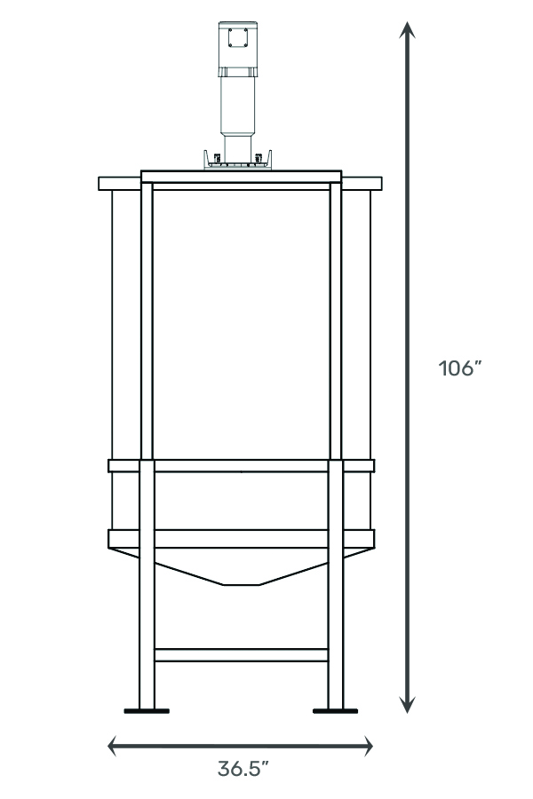
TS-350 (Gallon)
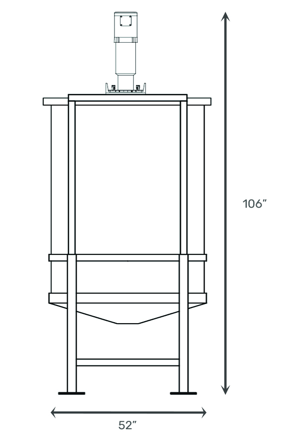
TS-500 (Gallon)
Recommended spacing between the wall and rear of the machine is 18” minimum for ease of access and serviceability. More space is recommended, maintain as much room behind or to the side of the machine for nutrient stock tanks. Follow all local codes when placing the machine in the space. Maintain a minimum 3ft distance in front of the machine for maintenance and accessibility and to allow the control cabinet door to safely open.
A forklift or a pallet jack may be used to maneuver the equipment into place. Ensure there is a viable path prior to moving the AFS to the desired location. Follow all required electrical and building codes for minimum clearances needed.
Notes
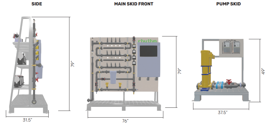
The Inline Series AFS will come with a pumping system that consists of one, or two, VFD controlled irrigation pumps. The primary side of those pump(s) should be flooded by the main fresh water source (1.5” input) as coordinated by your Rhythm PM. The output side of the pumps will connect with a 1.5” plumbing line to the input of the Inline Series AFS located on the bottom left of the machine (custom layout options may vary by project).
All Inline Series units come with a 1.5” Schedule 80 PVC output following the sensing section (pH/EC/Temp) of the unit. Optional Rhythm-built solenoid valve manifolds may also be included with the system. These valve manifolds, either provided by Rhythm or customer, should be plumbed (by customer) to each grow room and/or reservoir as coordination with your Rhythm Project Manager. A single output should be plumbed to a drain location in the facility
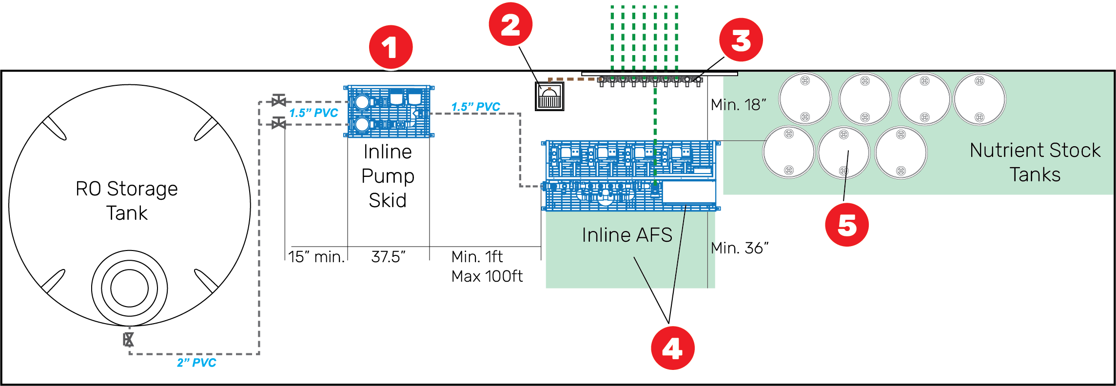
1 - Pump Skid: Location is flexible and should be placed near RO storage tank(s). Plumb suction side from tank(s) to skid inlet. Plumb pressure side from outlet to Inline AFS skid.
2 - Inline AFS Dump: The Inline system will require a dump output be plumbed to a local floor sink capable of handling up to 25 GPM.
3 - Inline AFS Delivery: Varies depending on how job is sold. Options include manifold distribution, or mainline distribution to grow rooms, or day-storage tanks.
4 - Inline AFS User Interface & Maintenance Clearance: Maintain at least 3ft in front of the skid for maintenance and interface.
5 - Nutrient Stock Tanks: The Inline AFS dosing pumps can draw from any type or size container, including hard-piped options from cone-bottom tanks. Containers may be placed adjacent to the left or right of the skid, or behind the skid, if the skid placement is located in the middle of a room.
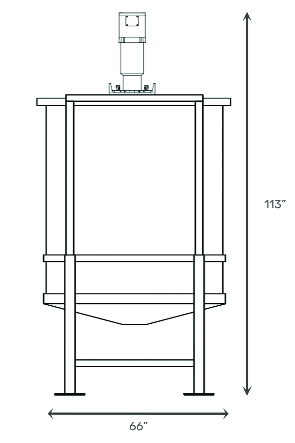
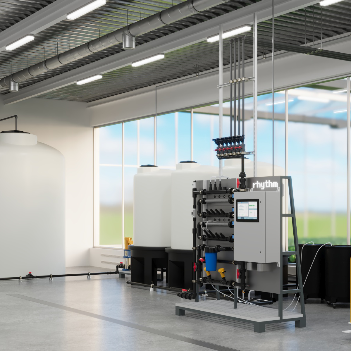
Example of large nutrient stock tank placement for Inline systems
Accommodations for nutrient stock/storage tanks should always be considered. These tanks will need to be located somewhere in the vicinity of the Inline Series machine. The size and location of those tanks should be driven by the specifics of the project (i.e. nutrient program, volumes used, irrigation room details, etc). Rhythm coordination/design services(included with equipment purchase) can assist in tank sizing and locations.
Notes
The Inline Series AFS will come with a pumping system that consists of one, or two, VFD controlled irrigation pumps. The primary side of those pump(s) should be flooded by the main fresh water source (1.5” input) as coordinated by your Rhythm PM. The output side of the pumps will connect with a 1.5” plumbing line to the input of the Inline Series AFS located on the bottom left of the machine (custom layout options may vary by project).
All Inline Series units come with a 1.5” Schedule 80 PVC output following the sensing section (pH/EC/Temp) of the unit. Optional Rhythm-built solenoid valve manifolds may also be included with the system. These valve manifolds, either provided by Rhythm or customer, should be plumbed (by customer) to each grow room and/or reservoir as coordination with your Rhythm Project Manager. A single output should be plumbed to a drain location in the facility
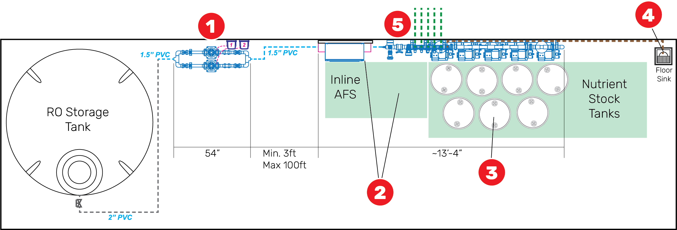
1 - Pump Skid: Location is flexible and should be placed near RO storage tank(s). Plumb suction side from tank(s) to skid inlet. Plumb pressure side from outlet to Inline AFS skid.
2 - Inline AFS User Interface & Maintenance Clearance: Maintain at least 3ft in front of the controller and equipment for maintenance and interface.
3 - Nutrient Stock Tanks: The Inline AFS dosing pumps can draw from any type or size container, including hard-piped options from cone-bottom tanks. Containers may be placed directly out in front of system, or adjacent to the left or right.
4 - Inline AFS Dump: The Inline system will require a dump output be plumbed to a local floor sink capable of handling up to 25 GPM.
5 - Inline AFS Delivery: Varies depending on how job is sold. Options include manifold distribution, or mainline distribution to grow rooms, or day-storage tanks.


.svg)