PLEASE READ CAREFULLY, FAILURE TO FOLLOW THESE PROCEDURES CAN RESULT IN DAMAGE TO YOUR SYSTEM AND VOID YOUR WARRANTY. Always abide by local plumbing codes when installing the system.
Upon delivery, inspect packaging and report any damage to the carrier and to Rhythm WITHIN TWO DAYS OF RECEIVING. After unpacking the system, inspect it carefully for signs of damage. All damage claims should be made to the delivery carrier or through Rhythm if we scheduled the shipment. In most instances, your shipments are insured by the carrier for up to $100,000.
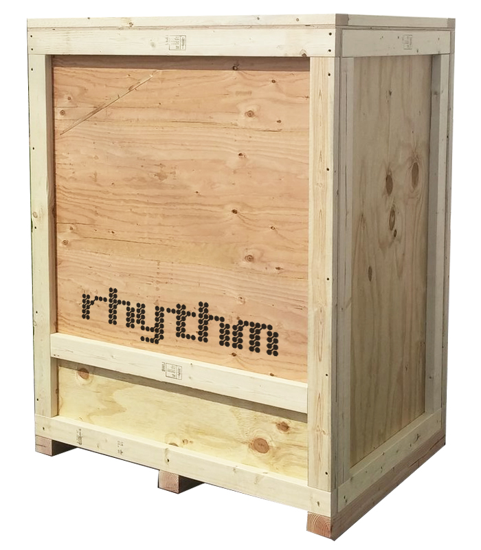
Receiving your crates
Your shipment will come in fully enclosed crate(s) with a "Rhythm" label.
Forklift with Extensions Required
Because our crates are generally too tall to fit inside enclosed trucks, they will come on flat bed trailers and need to be lifted from the truck deck with a forklift (pallet jack cannot be used in this step). We request fork extensions to be used, but regular forks can be used in conjunction with straps around the crate to secure it safely.
From the point crates are on the ground, they can be moved around with a standard pallet jack.
Your system is equipped with a variable number of calibration sensors. These sensors cannot be frozen or they will malfunction. Please do not store equipment in below freezing temperatures, or if you must, please remove sensors and move them to a warmer location.
Once your item is unpacked, you can move it to its predetermined final working place. This location has been chosen and engineered for your setup, so please refer to your personalized Coordination Documents for exact placements. Freely move entire unit with pallet jack. Please see System Dimensions & Clearances page for required clearances from walls. You are not required to bolt single batch systems to the ground but it is recommended to do so. Rhythm has provided bolt tabs on the machine feet for this purpose.
Connecting the manifold to your rooms
Twelve (12) 1” or 1-1/2” PVC (Socket Fitting) main fertigation outputs and one (1) dump output are located along the top-rear of the skid assembly. PVC fertigation mains and dump shall be plumbed from the outputs provided, to the desired location within the grow facility (This can be your rooms, separate reservoirs, or tables/racks.) Output #13 is ONLY for the Dump Feature. DO NOT PLUMB DUMP OUTPUT #13 TO IRRIGATION ZONES. Plumb the DUMP line to your floor drain, a sink, or wherever your designated dumping zone is. Secure the incoming PVC plumbing to the wall/ceiling above the AFS. Your plumber is required to plumb everything beyond the manifold to the rooms and PVC is not provided by Rhythm. The skid should be set along a wall, maintaining approximately 18-24” clear space behind unit for access and ease of maintenance. Offset plumbing fittings or trapeze hangers may be required to properly secure plumbing to align with AFS fertigation outputs.
Label each plumbing line with which zone it correlates to during installation. i.e. label the first fertigation output as "Veg Room 1" if that is what it is going to water. This will help when trying to manually shut off zones at the manifold level or when encountering any plumbing issues in the future.
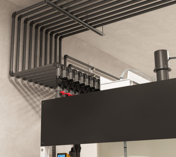
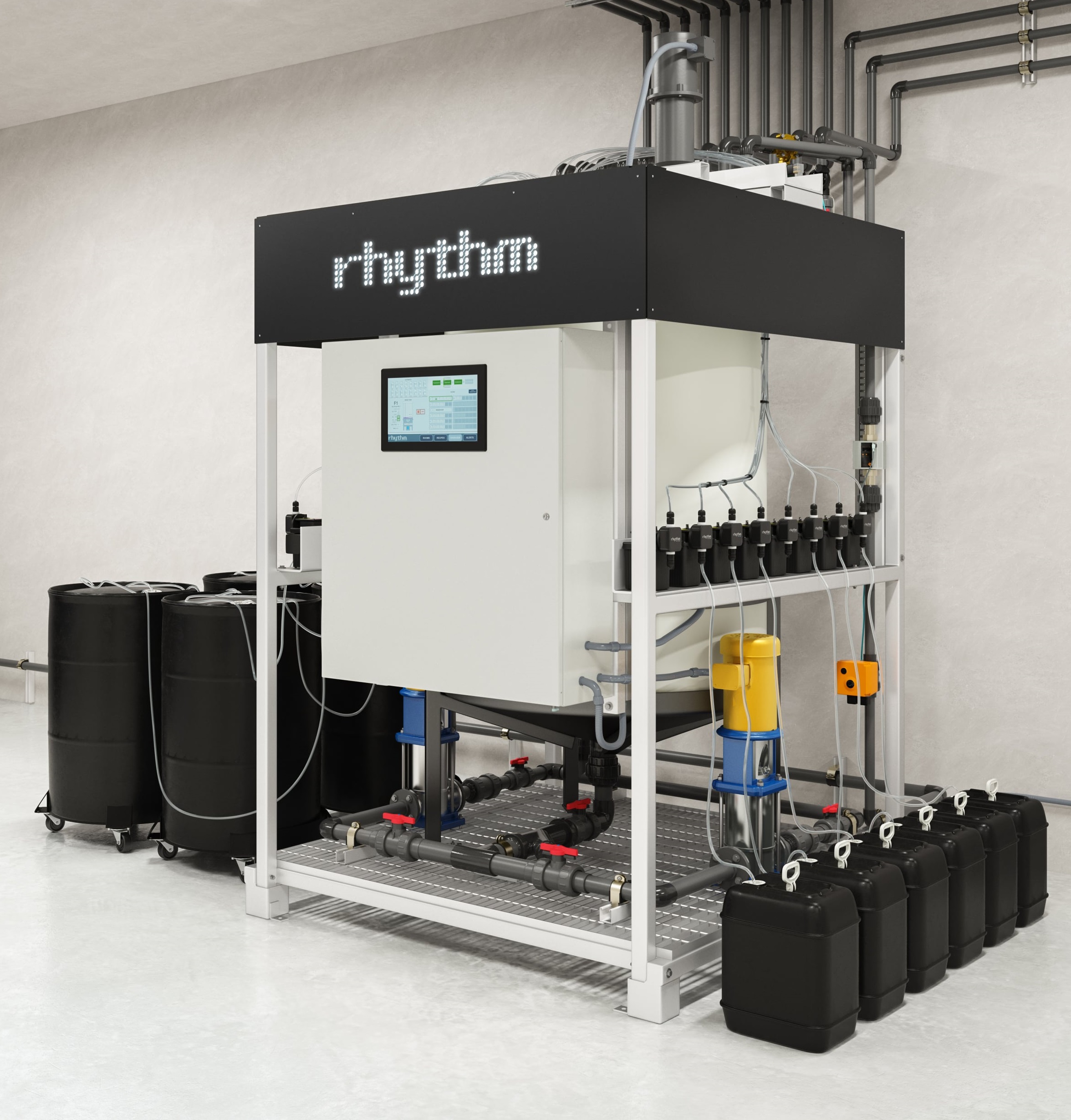
Example of single batch fertigation output installation configuration.
Connecting the water line
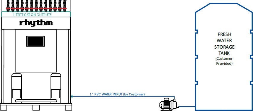
At the lower right corner of the skid, there is a union at the end of a slip connection for a 1" PVC connection. Plumb from your water source (usually a tank) to this simple connection on the skid to supply the machine with water. See diagram below.
Your water source and booster pump
While the AFS can work with a city or well tap, it is recommended to provide the AFS with low EC water that has been run through an industrial reverse osmosis system like Hydrologic.
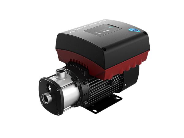
Rhythm does not provide the water tank or booster pump for pushing water to the machine. You will need to furnish and install a holding tank for fresh water supply with a booster pump capable of supplying the AFS with fresh water. We recommend this booster pump by Grundfos.
The holding tank should be sized according to maximum expected daily usage. The pump must be able to flow water at a max of 50 GPM and must shut itself off automatically when pressure of 60psi is achieved.
Power the machine
WARNING The system can start at any time when the power is connected. Do not connect power until the system is completely installed and ready to be run and tested.
Always abide by local electrical codes when installing the system and use a qualified, licensed electrical contractor.
Electrical requirements. The Single Batch AFS requires a single, dedicated, 40AMP, 120/240VAC dedicated circuit, with a neutral, and a 60 AMP local disconnect to be provided by your electrician. The AFS comes equipped with a 15ft power cord and is to be field wired by your electrician to the Disconnect. Mount this Disconnect within approximately 10ft of the AFS location.
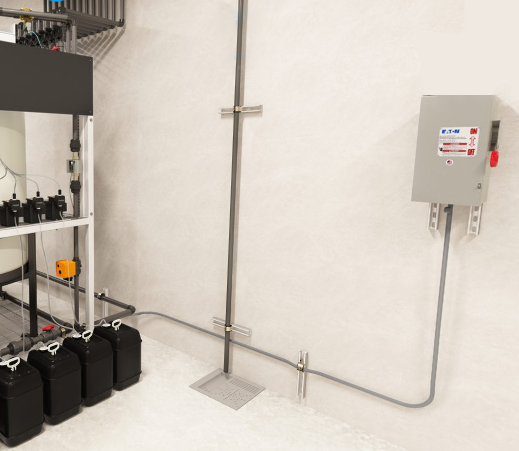
The power whip will be provided to you at the back of the machine. Connect this to your local Disconnect.
An example of a single batch machine connected to the local Disconnect via power whip.
Remote control cabinets. If your project has ancillary control cabinets, these will need to be mounted to the wall or a standalone support. Your electrician will need to provide a water tight entry point for all power and electrical coming into the control cabinet. An electrical trough is recommended to be installed below the cabinet to capture all the incoming power and low-voltage connections. Your electrician will need to pull wires from your power center/breaker, and bring them to three (3) entry-points into the bottom of the Rhythm cabinet from the trough. Rhythm will terminate the wires into the control cabinet during the commissioning procedure.
Connect the machine to the Internet
Generally, a hardline from your router will need to be run to the Rhythm controller as Rhythm will make a network through the hub cabinet. Specific details on which lines to run and where will be detailed in your personal Coordination Documents.
Note: Internet service is REQUIRED TO BE ON during start-up commissioning. Please make arrangements for this as it is required for full functionality.
Connect the nutrient containers
On a single batch, the dosing pumps will already be mounted on the skid. Locate the box we provided which houses the clear dosing tubing.
Example of nutrient placement for Single Batch systems
Maximum nutrient tubing included with the system is 5ft per dosing pump. Replacement or supplementary tubing can be purchased at any home improvement store, the sizing would be 1/4" ID (inner diameter) x 3/8" OD (outer diameter).
Nutrient containers can be placed above, horizontal to, or below dosing pumps. Please note, when placing containers below, the maximum distance from the pump head to the nutrient container should be less than 10 feet due to lift power of the pumps.
Multi-Batch units (AFS-MB200, AFS-MB350, AFS-MB500)
Once your item is unpacked, you can move it to its predetermined final working place. This location has been chosen and engineered for your setup, so please refer to your personalized Coordination Documents for exact placements. Freely move entire unit with pallet jack. Please see System Dimensions & Clearances page for required clearances from walls. You are not required to bolt multi-batch systems to the ground but it is recommended to do so. Rhythm has provided bolt tabs on the main machine feet and on the tank stands' feet for this purpose.
Freely move the "center section" machine with a pallet jack to its predetermined wall, then move the tanks with a pallet jack, one to each side of the center section.
Tanks are NOT INTERCHANGEABLE. Please refer to the labels "Tank 1" and "Tank 2" which should be written on your tanks. Tank 1 goes to the left of the center section and Tank 2 goes to the right.
Plumbing which connects the tanks to the center section is pre-assembled by Rhythm and can be connected simply by union to union connections. No glue required. See diagram above.
Connecting the manifold to your rooms
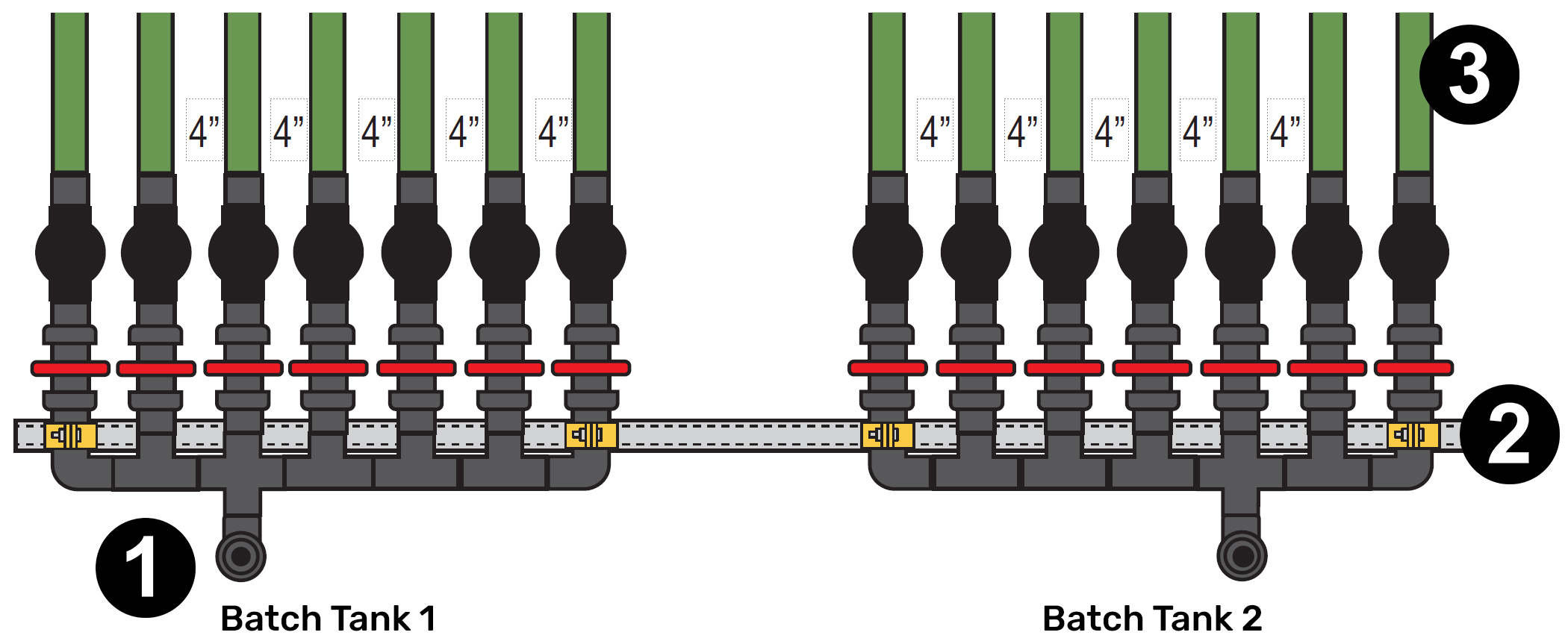
Multi-Batch units will have two (2) manifolds, one for each tank. The number of outputs will vary per customer, depending on your feeding needs. Consult your Coordination Documents for your project specific numbers.
Loose manifolds will be sent along with the center section and require connection to the center section by your plumber. See diagram below.
An EXAMPLE of what your manifolds may look like.
Follow the steps below to complete installation of the manifolds.
1. Connecting the union to the back of the Rhythm machine. Connect 1.5” Pre-cut plumbing connection piece to main AFS outputs. These are union connections on both ends, provided and labeled by Rhythm for tank 1 and tank 2.
2. Secure the manifold to the back wall. Secure the PVC plumbing to the wall behind the AFS. This part of the install is up to your plumber. The skid should be set along a wall, maintaining approximately 30-36” clear space behind unit for access and ease of maintenance. Offset plumbing fittings are usually provided by Rhythm. If not, please use some cushioned clamps or trapeze hangers to properly secure plumbing to align with AFS fertigation outputs.
3. Plumb the outputs to your grow rooms. The main 1” or 1-1/2” PVC (Socket Fitting) main fertigation outputs and one (1) dump output PER MANIFOLD shall be plumbed from the outputs provided, to the desired location within the grow facility (This can be your rooms, separate reservoirs, or tables/racks.) The output on the furthest RIGHT side of each manifold is ONLY for the Dump Feature. DO NOT PLUMB THESE DUMP OUTPUTS TO IRRIGATION ZONES. Plumb the DUMP line to your floor drain, a sink, or wherever your designated dumping zone is. Your plumber is required to plumb everything beyond the manifold to the rooms and PVC is not provided by Rhythm.
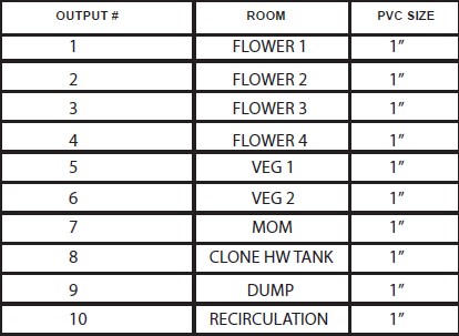
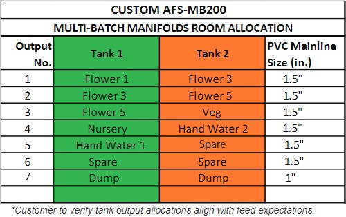
In your coordination documents, you will be given a chart based on YOUR SPECIFIC PROJECT which will guide your plumber where to route each output on the manifold:
An EXAMPLE of a chart used to route the outputs on your manifold. Please check your personal documents for exact chart.
Label each plumbing line with which zone it correlates to during installation. i.e. label the first fertigation output as "Veg Room 1" if that is what it is going to water. This will help when trying to manually shut off zones at the manifold level or when encountering any plumbing issues in the future.
Connecting the water line
At the lower right corner of the skid, there is a union at the end of a slip connection for a 1" PVC connection. Plumb from your water source (usually a tank) to this simple connection on the skid to supply the machine with water. See diagram below.
Your water source and booster pump
While the AFS can work with a city or well tap, it is recommended to provide the AFS with low EC water that has been run through an industrial reverse osmosis system like Hydrologic.
Rhythm does not provide the water tank or booster pump for pushing water to the machine. You will need to furnish and install a holding tank for fresh water supply with a booster pump capable of supplying the AFS with fresh water. We recommend this booster pump by Grundfos.
The holding tank should be sized according to maximum expected daily usage. The pump must be able to flow water at a max of 50 GPM and must shut itself off automatically when pressure of 60psi is achieved.
Power the machine
WARNING The system can start at any time when the power is connected. Do not connect power until the system is completely installed and ready to be run and tested.
Always abide by local electrical codes when installing the system and use a qualified, licensed electrical contractor.
Electrical requirements. The Multi-Batch AFS requires a single, dedicated, 40AMP, 120/240VAC dedicated circuit, with a neutral, and a 60 AMP local disconnect to be provided by your electrician. The AFS comes equipped with a 15ft power cord and is to be field wired by your electrician to the Disconnect. Mount this Disconnect within approximately 10ft of the AFS location.
The power whip will be provided to you at the back of the machine. Connect this to your local Disconnect.
An example of a single batch machine connected to the local Disconnect via power whip.
Remote control cabinets. It is likely that your project has ancillary control cabinets. These will need to be mounted to the wall or a standalone support. Your electrician will need to provide a water tight entry point for all power and electrical coming into the control cabinet. An electrical trough is recommended to be installed below the cabinet to capture all the incoming power and low-voltage connections. Your electrician will need to pull wires from your power center/breaker, and bring them to three (3) entry-points into the bottom of the Rhythm cabinet from the trough. Rhythm will terminate the wires into the control cabinet during the commissioning procedure.
Connect the machine to the Internet
Generally, a hardline from your router will need to be run to the Rhythm controller as Rhythm will make a network through the hub cabinet. Specific details on which lines to run and where will be detailed in your personal Coordination Documents.
Note: Internet service is REQUIRED TO BE ON during start-up commissioning. Please make arrangements for this as it is required for full functionality.
Install dosing pump panel
On a multi-batch, the dosing pumps will be mounted to a dosing pump wall. You will be supplied with the dosing wall(s), the dosing pumps (in their original packaging), and some clear poly tubing rolls.
Set the dosing panel(s) alongside the wall predetermined in your Coordination Documents. Please allow for room BEHIND the dosing panel as it will need to be accessed during commissioning. Dosing panels MUST be bolted to the ground using the bolting tabs on the unistrut feet. Connect the supplied power whip(s) behind the panel(s) into the Rhythm control cabinet as shown on your Coordination Documents. Rhythm will make the final terminations in the cabinet during onsite startup. During installation, keep in mind that nutrient containers will go in front of the dosing panels so make sure there is ample room in front.
Note: You do NOT NEED TO INSTALL THE DOSING PUMPS ONTO THE PANEL. A Rhythm installer will do this during the start-up commissioning process.
Rhythm-installed items
Your crate will come with some items that are designated for Rhythm installer's use only. Please place these items in the area of the Rhythm layout site as loss or damage to them will incur a fee. These items include but are not limited to:
• pH/EC sensors. There will be boxes labeled "GF Signet" that will contain your pH and EC sensors. Please keep these in a climate controlled area. They will be installed by Rhythm.
• Roll(s) of clear, poly tubing. This is used for the dosing pumps and will be routed from your dosing pump wall to the batch tank by a Rhythm installer.
• Dosing pumps. These will come in their original packaging and contain vital parts for installation. Please do not open them and place them by the dosing pump wall for Rhythm to install.
• Stainless mixer shaft and propeller. The shaft may be attached to the "center section" skid and will be installed into the tank by Rhythm.
• Fusion electric mixer. These may be strapped to the top of the tank cross bar, or they may have been sent in their original packaging. You do not need to install these, a Rhythm installer will assemble and connect them at startup.
Custom Layout non-skid units and AFS-B500 units
All projects will be supplied with personal Coordination Documents for you to reference when assembling your layout. The location will be predetermined with you and your contractors and electrical junction boxes and power connections should be made available by your electrician. Custom layout jobs require a bit more placement steps than skid-based systems. Go through the following steps to make sure your system is properly set:
1. Placing the batch tank(s). Custom multi-batch projects will have two tanks. Please refer to your Coordination Documents for exact placement of your tank stand(s) as the orientation matters. For custom layouts, tanks need to be bolted to the ground using the provided frame tabs on the base of the tank stand.
2. Install the electrical mixer atop the batch tank. The mixer labeled "Fusion" will come in its original packaging. Remove the mixer (it is very heavy) and place atop the batch tank cross bar. There will be holes in the cross bar for easy placement. Rhythm will have supplied you with nuts/washers for assembly.
Important Note:The box containing the Fusion mixer may also include the shaft propeller. PLEASE DO NOT MISPLACE THIS as it is required and will be later installed by Rhythm.
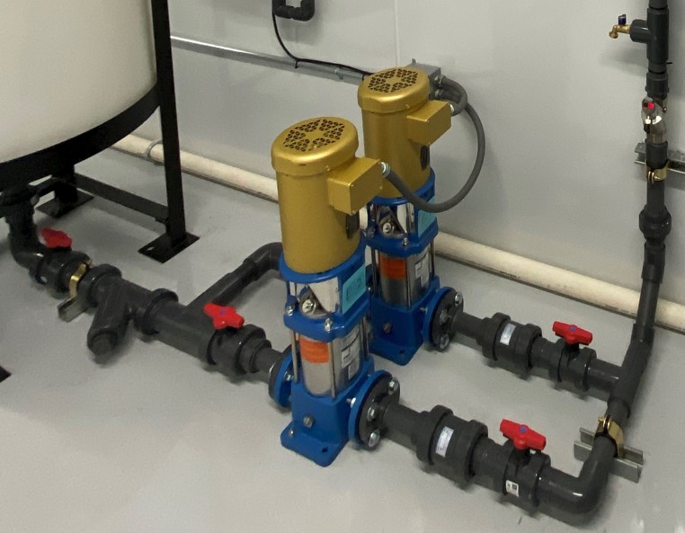
3. Set the irrigation pumps(s). Detailed drawings will be given to you about where to place your pumps, but there is some liberty based on the arrangement of your space. Rhythm will have provided pre-plumbed sections to connect the irrigation pump(s) to the batch tank(s) for a set distance between the two.
4. Connect the pump(s) to the batch tank. The Rhythm-provided plumbing sections will include the Y-strainer, the check valves, and some shutoff valves. Using these provided plumbing sections, attach the irrigation pump(s) to each other, to the batch tank, and to the sensor riser.
Note: If your system has two pumps instead of one, connector plumbing sections will be supplied by Rhythm and can be plumbed and arranged like the following example:
Use the Rhythm provided plumbing section with the Y-strainer to plumb from the bottom of the tank union to the irrigation pump flange. The flange side will require bolting. See image above for orientation.
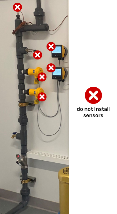
5. Assemble the sensor riser. The sensor riser will comprise of the inline flow meter, hose bibb, the sensor tee connectors, and the pressure transmitter. The riser may be shipped to you in full, or in two/three pieces. The pieces should be labeled but you can also see your Coordination Documents to get a visual representation of how the riser will be connected. The sensor riser can be attached to the wall using the provided unistrut and cushioned clamps.
Note: Your shipment will come with the GF Signet Sensors (ph probes and EC sensors). PLEASE DO NOT INSTALL THESE ONTO THE PLUMBING RISER. A Rhythm installer will install these items during commissioning.
6. Connect the pump(s) to the sensor riser. Use the Rhythm provided plumbing section with the check valve to attach the pump to the sensor riser. The pump side will require bolting the flange and the opposite end will depend on how far your riser is from the wall that you attach it to. You will need to measure and cut some 1" PVC to connect elbow to elbow. Please use the provided cushioned clamps with unistrut to secure the plumbing to the floor.
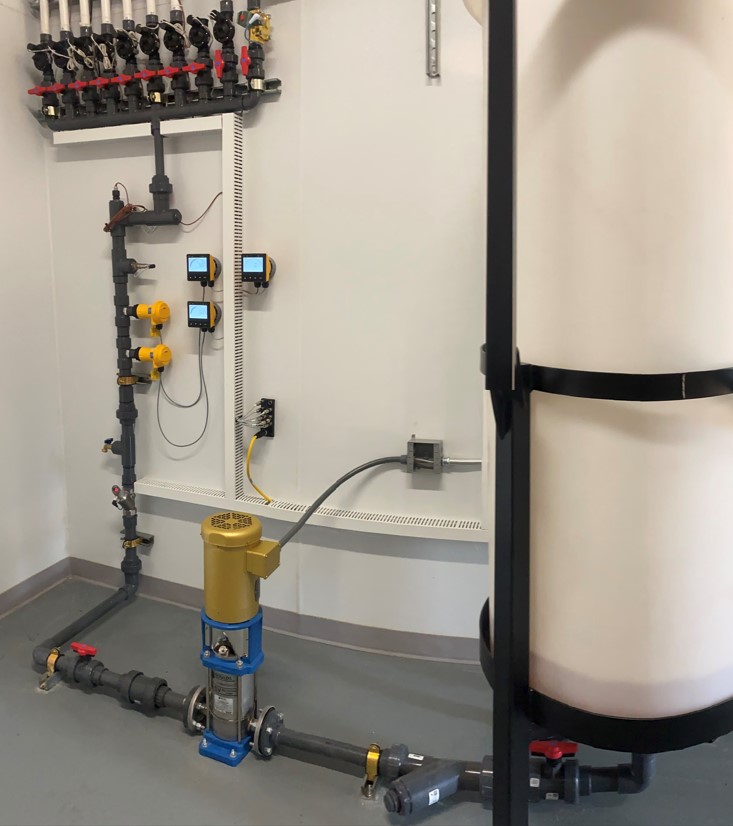
7. Connect the sensor riser to the manifold. The sensor riser can be easily connected to the manifold simply by union-to-union connection. See the image below for a complete picture of how the completed assembly will look:
8. Mount the manifold and route to your Rooms. Custom layout units have one manifold per batch tank. The number of outputs will vary per customer, depending on your feeding needs. Consult your Coordination Documents for your project specific numbers. Manifolds should be mounted to the wall and adjoin with the plumbing coming from the irrigation pump. This distance may vary.
The manifold will include x number of outputs for your rooms/reservoirs, 1 output dedicated for dump, and 1 output dedicated for the recirculation. DO NOT PLUMB THE DUMP OR RECIRCULATION OUTPUTS TO IRRIGATION ZONES. Your plumber is required to plumb everything beyond the manifold to the rooms and PVC is not provided by Rhythm. Plumb the DUMP line to your floor drain, a sink, or wherever your designated dumping zone is.
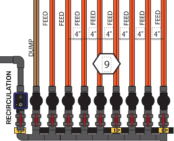
You will be given an illustration and a chart for where to route your outputs. See example below:
An EXAMPLE of what your manifold may look like.
An EXAMPLE of a chart used to route the outputs on your manifold. Please check your personal documents for exact chart.
Label each plumbing line with which zone it correlates to during installation. i.e. label the first fertigation output as "Veg Room 1" if that is what it is going to water. This will help when trying to manually shut off zones at the manifold level or when encountering any plumbing issues in the future.
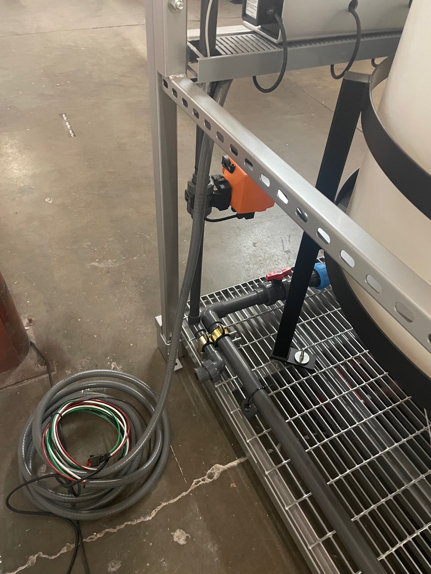
9. Plumb the recirculation output into the batch tank. The recirculation or agitation output will be easily identified by the adjoining valve. The appearance can vary per customer but it is usually brass or blue. You will only need to plumb to the union connection inside the tank which will be labeled by Rhythm as "RECIRC" or "AGITATION". See image below for a visual representation of the installation.
10. Plumb the fresh water line into the batch tank. You will be provided with a plumbing section that will consist of the flow meter and motorized valve (usually orange). Use 1" PVC and elbows to plumb one end into the batch tank and one end to your water source. You will only need to plumb to the union connection inside the tank which will be labeled by Rhythm as "FRESH WATER". See image above for a visual representation of the installation. Your plumber is required to route the line from the batch tank through the booster pump and terminate at the water stock tank. This part of the 1" PVC is not included or installed by Rhythm.
Your water source and booster pump
While the AFS can work with a city or well tap, it is recommended to provide the AFS with low EC water that has been run through an industrial reverse osmosis system like Hydrologic.
Rhythm does not provide the water tank or booster pump for pushing water to the machine. You will need to furnish and install a holding tank for fresh water supply with a booster pump capable of supplying the AFS with fresh water. We recommend this booster pump by Grundfos.
The holding tank should be sized according to maximum expected daily usage. The pump must be able to flow water at a max of 50 GPM and must shut itself off automatically when pressure of 60psi is achieved.
Installing electrical components
WARNING The system can start at any time when the power is connected. Do not connect power until the system is completely installed and ready to be run and tested.
Always abide by local electrical codes when installing the system and use a qualified, licensed electrical contractor.
Electrical requirements. The required power for custom jobs will vary, and depends on which and how many pumps your project has. For instance, 1 of the 2hp pump will require a 30A/240V dedicated circuit, and 2 pumps will require a 40A/240V. If your project is using 3hp pumps, you may only require a single 20A. Please consult your personal Coordination Documents for exact requirements.
11. Place the control cabinet. Your main control cabinet will need to be mounted to the wall or a standalone support. Your electrician will need to provide a water tight entry point for all power and electrical coming into the control cabinet. An electrical trough is recommended to be installed below the cabinet to capture all the incoming power and low-voltage connections. Your electrician will need to pull wires from your power center/breaker, and bring them to three (3) entry-points into the bottom of the Rhythm cabinet from the trough. Rhythm will terminate the wires into the control cabinet during the commissioning procedure.
Your electrician will also need to install a conduit raceway into the Rhythm cabinet, through trough, for 24V solenoid control wire coming from grow rooms.
Remote control cabinets. Your project may have ancillary control cabinets. These will need to be mounted to the wall or a standalone support. Your electrician will need to provide a water tight entry point for all power and electrical coming into the control cabinet. An electrical trough is recommended to be installed below the cabinet to capture all the incoming power and low-voltage connections. Your electrician will need to pull wires from your power center/breaker, and bring them to three (3) entry-points into the bottom of the Rhythm cabinet from the trough. Rhythm will terminate the wires into the control cabinet during the commissioning procedure.
12. Install conduit and junction boxes for Rhythm devices. Your electrician will be required to install junction boxes near the Rhythm layout for the tank's electric mixer, the motorized valve and the irrigation pump(s). Recommendations for the locations of these j-boxes can be found in your Coordination Documents. Complete the wiring of the devices in the following list:
• Motorized Valve. The motorized valve will have a short whip attached to it that you can simply pull to the closest j-box installed by your electrician. Consult your Coordination Documents for wiring information as it is up to your electrician to complete the wiring here. • Electric Mixer. Unscrew the wire housing on the mixer atop the batch tank and connect the wires with flex conduit (supplied by your electrician) to the nearest j-box installed by your electrician. Consult your Coordination Documents for wiring information as it is up to your electrician to complete the wiring here.
• Irrigation Pump(s). Unscrew the wire housing on the pump(s) and connect the wires with flex conduit (supplied by your electrician) to the nearest j-box installed by your electrician. Consult your Coordination Documents for wiring information as it is up to your electrician to complete the wiring here.
13. Place the dosing pump panel. Set the dosing panel(s) alongside the wall predetermined in your Coordination Documents. Please allow for room BEHIND the dosing panel as it will need to be accessed during commissioning. Dosing panels MUST be bolted to the ground using the bolting tabs on the unistrut feet. Connect the supplied power whip(s) into the Rhythm control cabinet as shown on your Coordination Documents. Rhythm will make the final terminations in the cabinet during onsite startup. During installation, keep in mind that nutrient containers will go in front of the dosing panels so make sure there is ample room in front.
Note: You do NOT NEED TO INSTALL THE DOSING PUMPS ONTO THE PANEL. A Rhythm installer will do this during the start-up commissioning process.
Rhythm-installed items
Your crate will come with some items that are designated for Rhythm installer's use only. Please place these items in the area of the Rhythm layout site as loss or damage to them will incur a fee. These items include but are not limited to:
• Junction block and yellow cable. This junction block with accompanying cable will be installed by Rhythm. • White fingerduct. This fingerduct will be used to route and hide wires from the junction block and pH/EC sensors and will be installed by Rhythm.
• pH/EC sensors. There will be boxes labeled "GF Signet" that will contain your pH and EC sensors. Please keep these in a climate controlled area. They will be installed by Rhythm.
• Roll(s) of clear, poly tubing. This is used for the dosing pumps and will be routed from your dosing pump wall to the batch tank by a Rhythm installer.
• Dosing pumps. These will come in their original packaging and contain vital parts for installation. Please do not open them and place them by the dosing pump wall for Rhythm to install.
• Stainless mixer shaft and propeller. The shaft will be installed into the tank by Rhythm.
Connect the system to the Internet
Generally, a hardline from your router will need to be run to the Rhythm controller as Rhythm will make a network through the hub cabinet. Specific details on which lines to run and where will be detailed in your personal Coordination Documents.
Note: Internet service is REQUIRED TO BE ON during start-up commissioning. Please make arrangements for this as it is required for full functionality.


.svg)


.jpg)


.jpg)