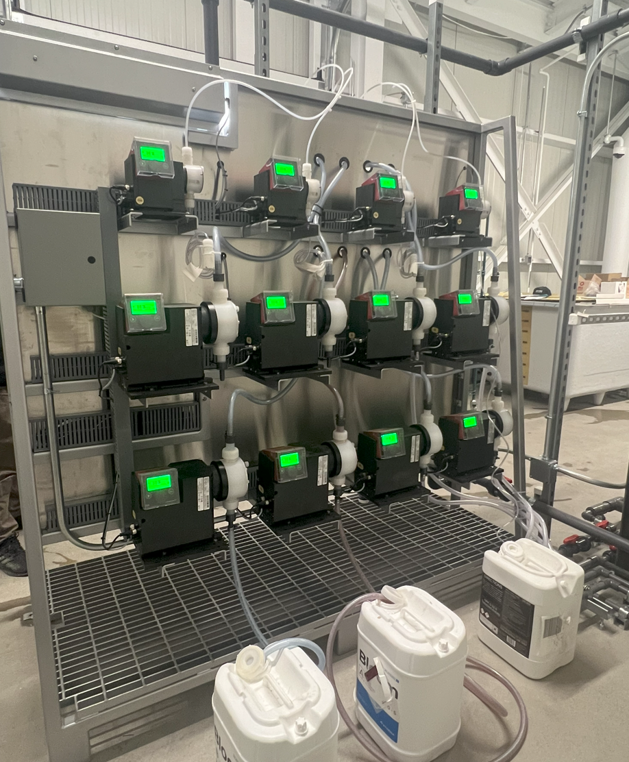
Connecting Nutrients. The nutrient dosing pumps are positioned on both sides of the skid assembly, 8 pumps on each side, 16-total. During configuration, each dosing pump will be assigned a specific nutrient, additive, or pH Up/Down. Set the appropriate nutrient containers on the floor, below the assigned pump, adjacent to the skid. Insert the tubing from the dosing pump, with the pre-assembled foot valve/strainer assembly, into the assigned container.
The nutrient tubing may need to be trimmed to fit properly. In such a case, remove the tube nut. Pull the clear suction tubing off the compression barb of the fitting. Trim the tube to the appropriate length. Push tubing back onto the compression barb and secure the tube nut. Hand tighten only.
The proper length of the tubing should allow the foot valve/strainer to rest in a vertical position, just touching the bottom of the nutrient container. If a particular nutrient tends to settle, the strainer may need to be picked up off the bottom of the container to prevent sediment from clogging and loss of prime from occurring.
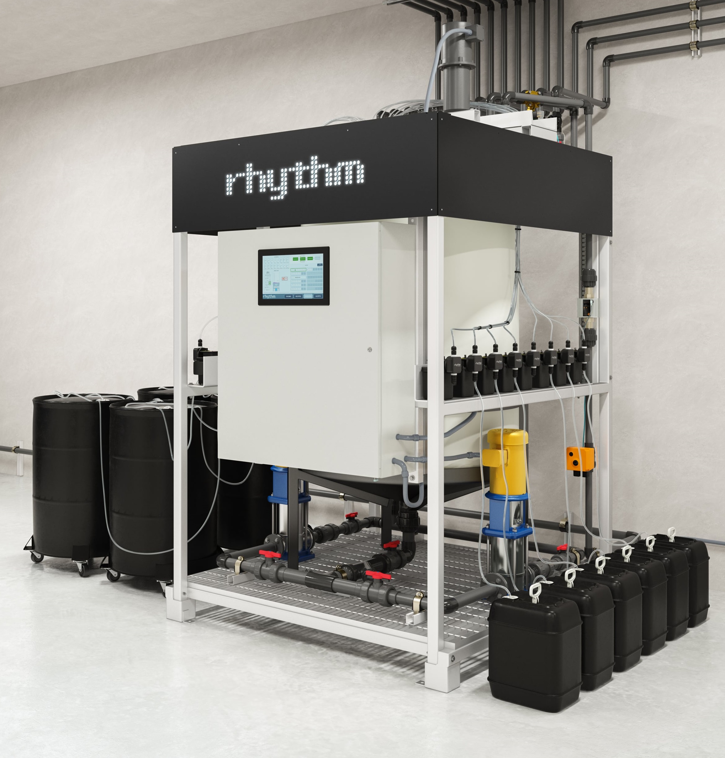
Example of nutrient placement for skid-based systems
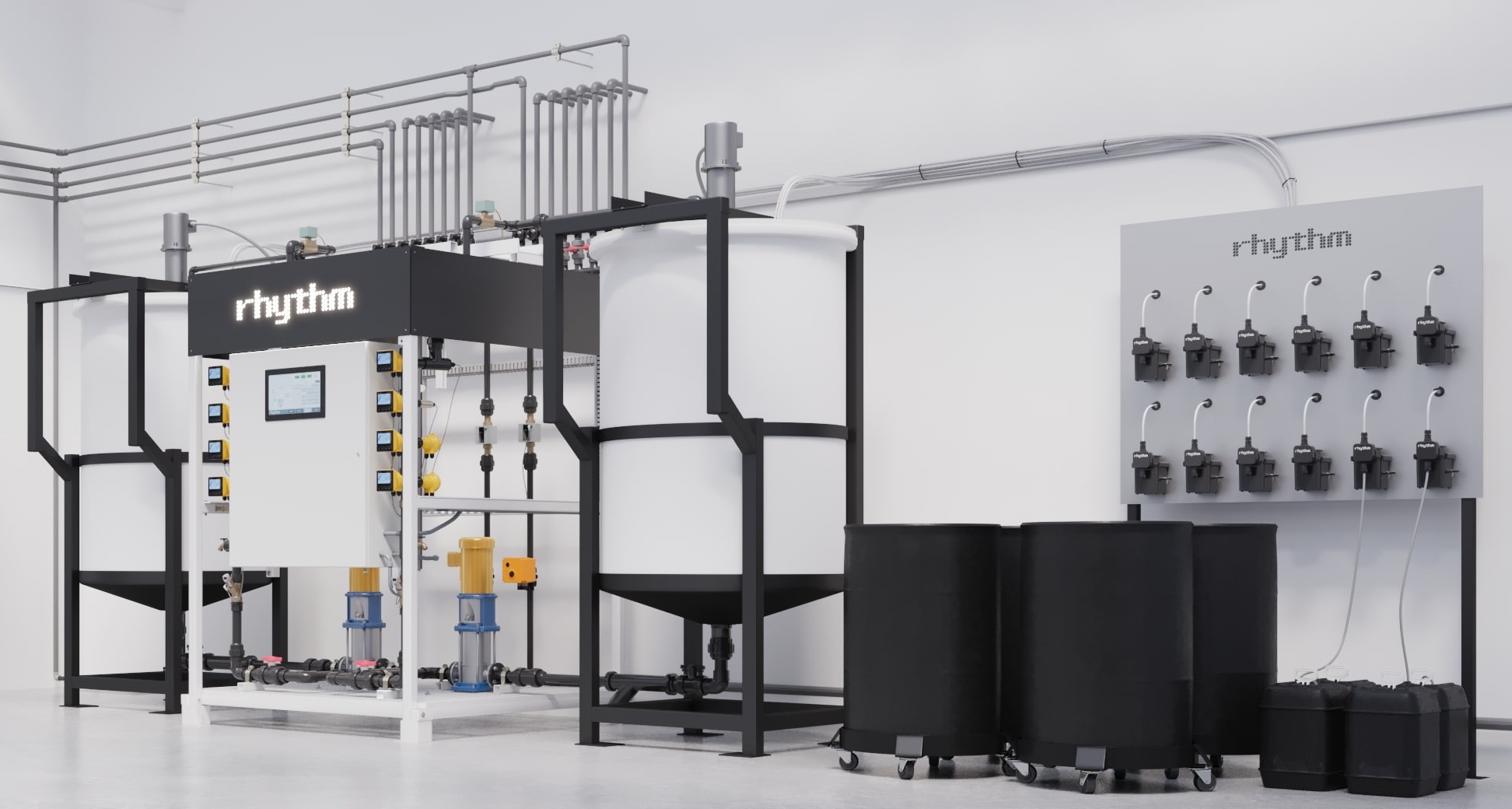
Example of nutrient placement for systems with a dosing panel
Rhythm includes 10ft of tubing per dosing pump. Replacement or supplementary tubing can be purchased at any home improvement store, the sizing would be 1/4" ID (inner diameter) x 3/8" OD (outer diameter).
Nutrient containers can be placed above, horizontal to, or below dosing pumps. Please note, the pumps are rated for 10ft of suction lift.
The Batch Series AFS may only be used with drip system friendly, liquid nutrients. Pre-mixed salts and powders are okay, as well are some organics. Contact your nutrient manufacturer to verify if your nutrient inputs are for use in drip irrigation systems. Failure to utilize a dosing friendly nutrient line may result in clogged injectors, dirty sensor probes, excessive build up in plumbing lines, and/or system failure.
The dosing pumps will require occasional cleaning, especially the Injection Fitting, the Foot valve/Strainer, and the pump head valves. The frequency will depend on the type and viscosity of the nutrient it is pumping, but we recommend cleaning once a month or whenever found to be clogged.
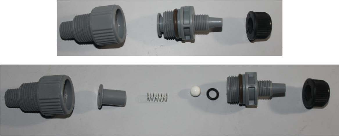
Clean the injection/check valve assembly. This is required especially when injecting fluids that calcify such as sodium hypochlorite. These lime deposits and other build ups can clog the fitting, increase the back pressure and interfere with the check valve operation. To clean the injection/check valve, unscrew all parts and disassemble. Rinse with warm water and soap as necessary. Reassemble and replace.
Injection/check valve assembly exploded view.
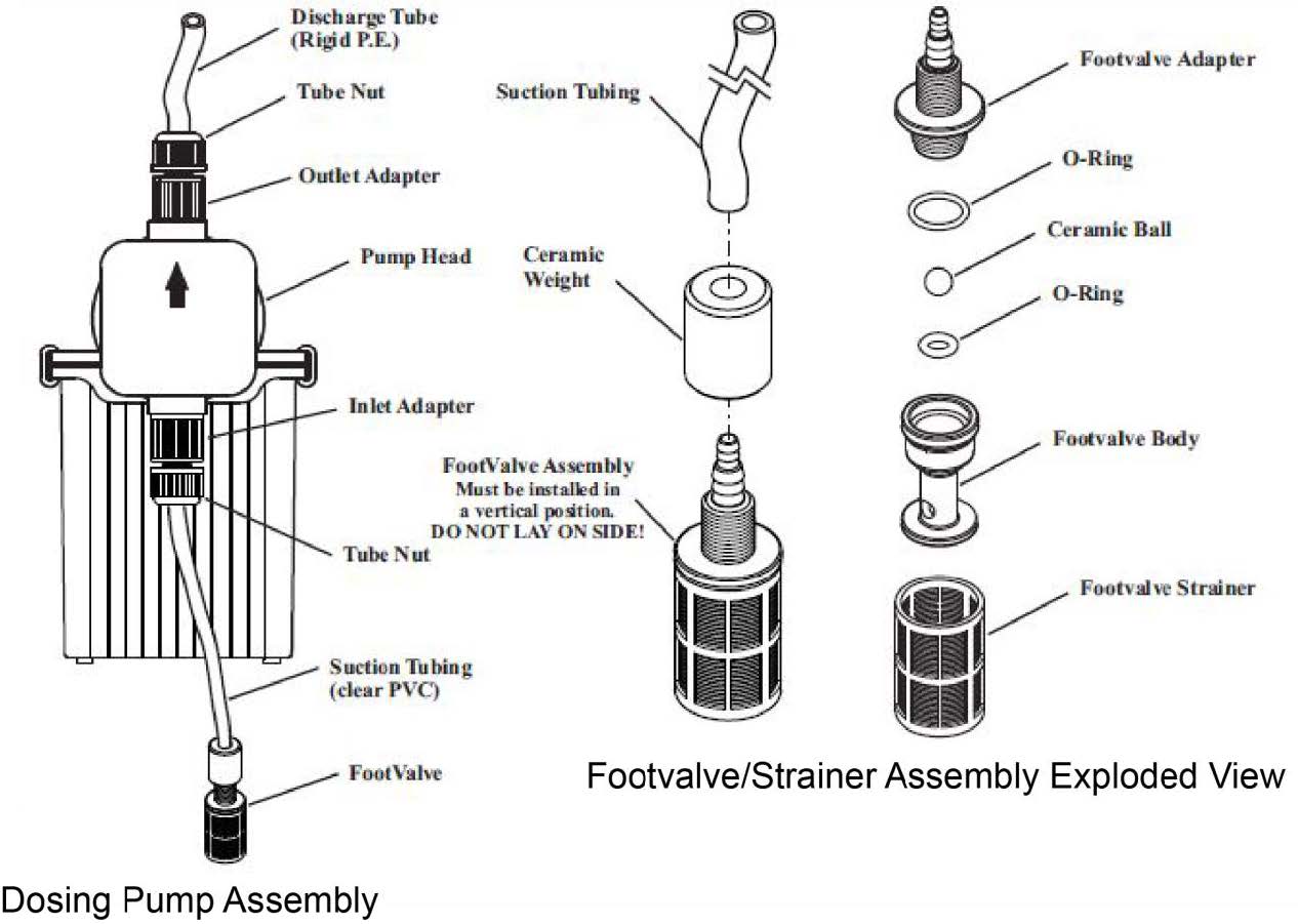
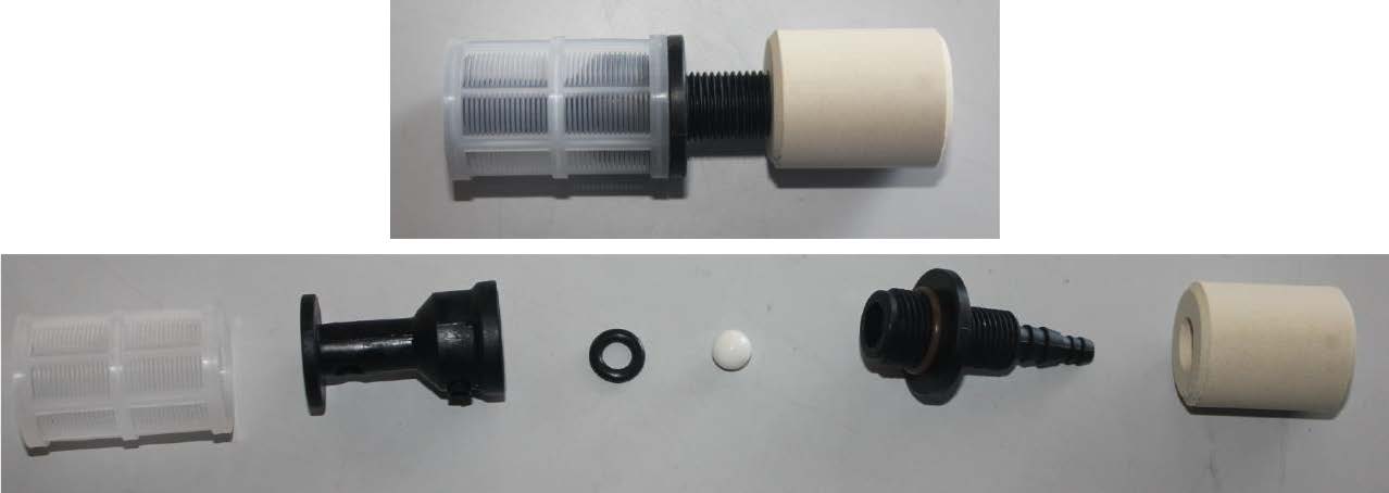
Clean the foot valve/strainer. Remove the foot valve and strainer attached to the tubing from the nutrient container and rinse with warm water. If it appears that a deeper clean is necessary, see Figure the image below on disassembly. Once disassembled, rinse all components with warm water and wipe away residue as necessary. Reassemble the foot valve/strainer and replace in nutrient container.
Nutrient dosing pump assembly and exploded component views.
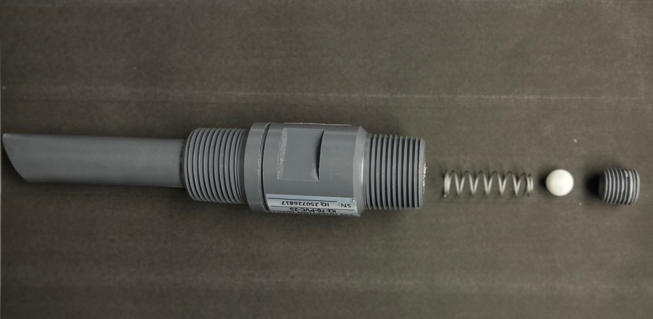
Foot valve/strainer assembly exploded view.
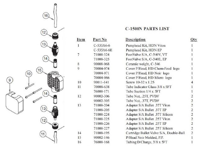
Cleaning the dosing pump head. If a pump appears to struggle to dose a particular nutrient, it may need to be cleaned. First start by removing the pickup line from the nutrient. Clean the the foot valve/strainer assembly and replace with a new 3/8” pickup tube. Place pickup in a container of warm, clean water and turn the pump on. Allow the pump to run clean water through it until it returns to normal pumping. If the pump continues to remain clogged, the internal pump head will need to be cleaned. First start by having an electrician disconnect power to the pump. Next, remove the plastic cover from the pump head. Remove the four screws that hold the head to the body. Carefully remove the pump head, rinse with warm water and wipe clean.Remove the adapter bullets (piece #13 in Figure 6-5 below) and rinse with warm water.Reassemble and replace the head assembly. After the head assembly has been rinsed and wiped clean, it is a good idea to pump warm water repeatedly through the pump to remove any possible build-up that may remain. Fill a bucket or jug with warm water. Place the pump suction tubing, with foot valve/strainer attached, into the bucket of warm water. Place the discharge tubing into an empty bucket and allow the pump to pump all the warm water through until no particles are seen coming through into the discharge bucket.
Dosing pump head exploded view.
Calibrating the Blue-White Dosing Pumps
Keeping the Rhythm Batch Series AFS dosing and sensing equipment calibrated will ensure accurate delivery of recipes, increase mix times, and overall improve the performance of the machine. Regular calibration is required for nutrient dosing pumps and pH / EC sensors. These procedures require no tools, hand tighten only! Use of pliers or tools will cause damage to the nuts and threads and can cause leaks.
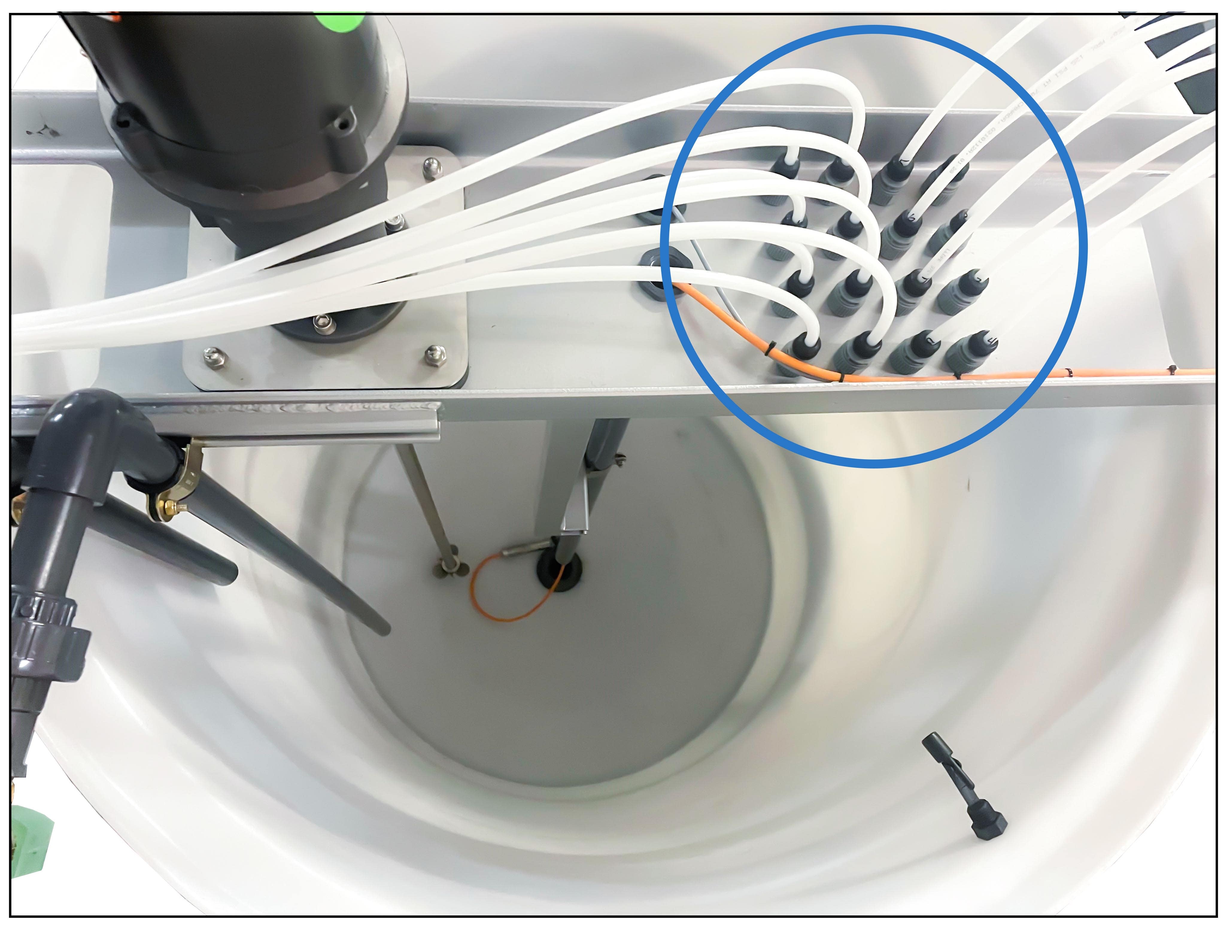
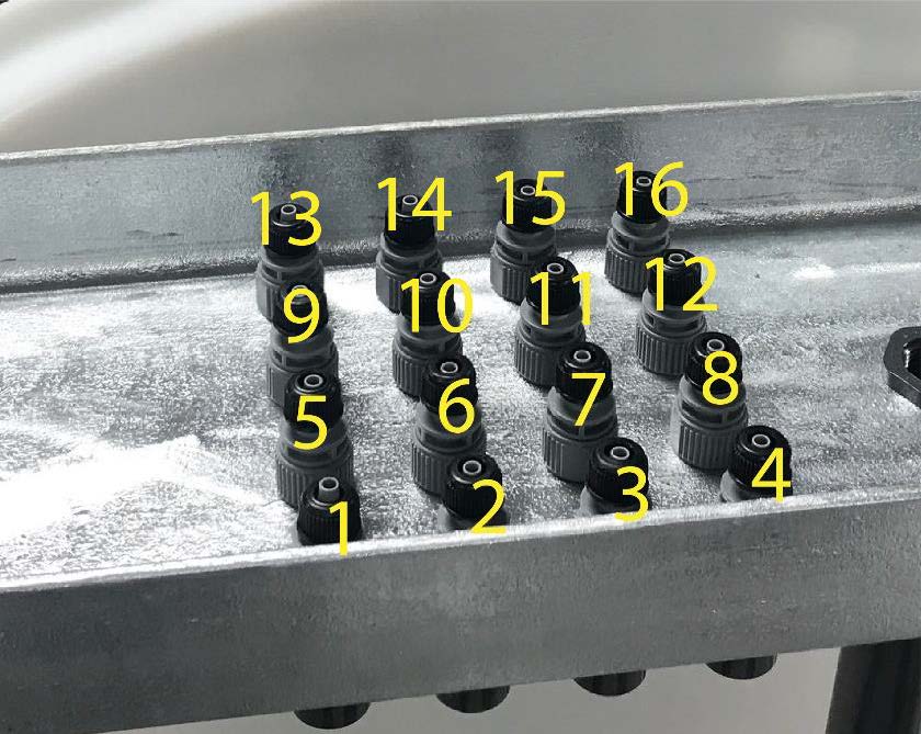
Dosing pump layouts. You can identify each dosing pump using the following diagrams. This will help when calibrating each nutrient.
The nutrient injectors are situated from front to back, left to right, and are labeled 1 through 16 (or however many dosing pumps your project has), which correspond with the dosing pumps. See the image below for the dosing pump numbering scheme. From front to back: Left side is 1 through 8. Right Side is 9 through 16.
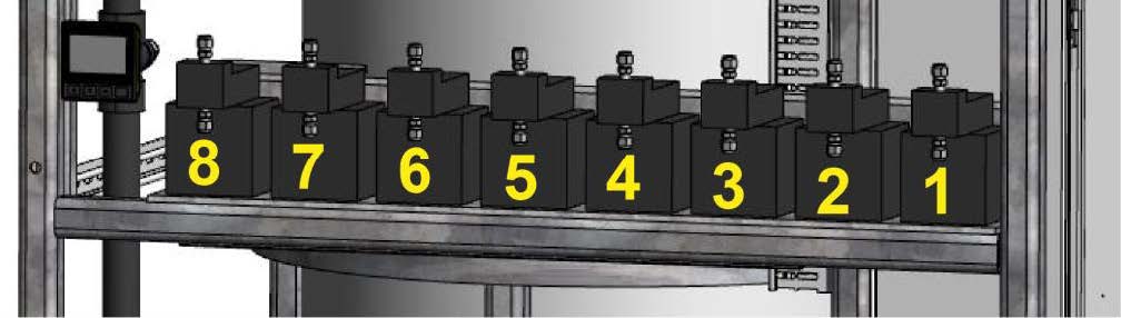
Pumps #1-8 on the left side. Pump #1 is the front of the skid.
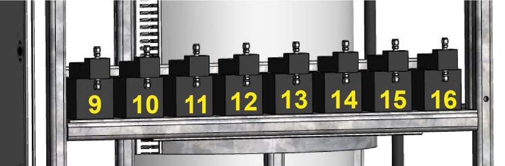
Pumps #9-16 on the right side. Pump #9 is the front of the skid.
Skid based systems nutrient pump numbering: LEFT side is #1-8 and RIGHT side is #9-16.
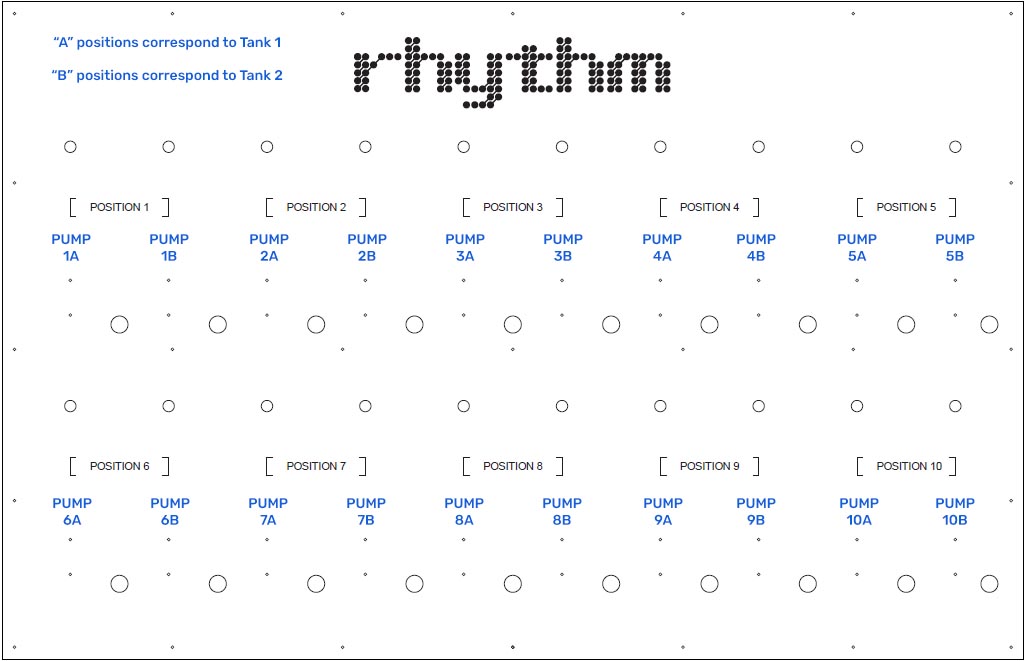
(Click image to view larger) System with a dosing panel nutrient pump numbering: "Position 1" will hold two places. The first place will correlate to dosing pump #1 for tank 1 (position 1A). The second place will correlate to dosing pump #1 for tank 2 (position 1B). Therefore, the grouping will continue as follows: 1A, 1B, 2A, 2B, 3A, 3B, etc.
Dosing pump calibration procedure. Calibrate the nutrient dosing pumps once every 3-4 months, or if EC begins to stray from known recipes, this could be an indication a dosing pump needs to be recalibrated. To calibrate each pump, you will need a 2000ml graduated cylinder and a ladder to access the injector/check valves located in the top cross brace over the mix tank.
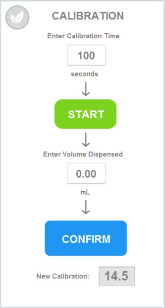
Step 1 • Position a large ladder at the left side of the AFS tank, with access to the nutrient dosing nozzles over the top of the tank. Step 2 • In the software, go to Rhythm Logo > Configuration > Nutrients > Click on the individual nutrient you'd like to calibrate. A popup titled "Position X" will appear and to the right of the popup you will see "Calibration."
Step 3 • Calibration time is recommended to be at 100 seconds for better accuracy but please note for high dose nutrients, you will want to use a large catch container, like a 2000ml measuring cup. Once you press "Start" you will have 10 seconds before the nutrient starts dispensing (it may be helpful to have a second person already at the tank). Once the nutrient you are trying to calibrate has finished dispensing for 100 seconds, remove and view the graduated cylinder on a flat and level surface. Record the amount inside your measuring cup in the "Enter Volume Dispensed" box and press confirm. This will populate a calibration value Rhythm will use to dispense your nutrients more accurately.
Repeat the process for every nutrient that needs calibrating. The nutrient that got dispensed into the measuring cup can be placed back into the original nutrient container for reuse.
Ordering Blue-White Replacements
Your Rhythm Batch Series AFS is equipped with many off-shelf parts and equipment, built for ease of repair or replacement. Additionally, your purchase comes with the following spare parts:
AFS spare parts kit
Qty – 2: 1" Netafim solenoid valve Qty – 5: Fuses
Replacing dosing pumps. If your pump is experiencing problems, please see the following section for Troubleshooting issues to see if the problem can be amended before considering a complete replacement. Sometimes, pumps will malfunction or be damaged by the user. In this case, contact Rhythm Support at 833-749-8461 or at support@rhythmcss.com to request support for replacing dosing pumps.
Blue-White Dosing Troubleshooting
1. A dosing pump is not pumping a nutrient.
If you can hear the pump motor turn on, but nothing pumps out, follow these steps to diagnose the issue:
• Priming the low dose pump. The initial pickup may be jammed. Turn the pump to max power by adjusting the knob on the top of the pump to "9", then grab the dosing line feeding into the nutrient container and jiggle the foot valve with the ceramic weight and filter around in the container so it can clear out air bubbles and start suctioning again. • Clean the injection/check valve and foot valve/strainer. It is likely the injector or foot valve is clogged. Certain nutrients with high salt contents that tend to settle or stick to surfaces, can clog the internals of the injector. See Cleaning the foot valve section above for detailed instruction and pictures of how to disassemble and clean these components.
• If this does not fix the issue, the pump itself may be clogged and need to be cleaned. You can first start by running warm water through it repeatedly to flush out the internals. First begin by removing the nutrient it is attached to and removing the suction tube and outlet tube from the pump. Remove the injector/check valve and foot valve strainer from the dosing tubing and make up a new clean tube that you can route from a bucket of fresh water, to an empty bucket. Supplementary tubing can be purchased at any hardware store in size 1/4" ID (inner diameter) x 3/8" OD (outer diameter). Once the tubing is in place, fill a bucket of water with WARM, fresh, clean water and place the suction side of the tubing into this bucket. Place the outlet tubing with the injector nozzle over the empty bucket. Turn on the pump and allow it to pump all of the water from one bucket to the next. You should start to see sediment and residual build up being flushed from the pump. Continue until only clean water comes out of the output side.
• Finally, if this still isn’t solving the issue, the pump head will need to be removed, and internal components flushed and cleaned. See the Cleaning the dosing pump head section above for details.
Contact Rhythm CSS customer for additional assistance if cleaning does not solve the issue.
2. A nutrient is settling or separating while sitting in the tank and doesn’t pump evenly over time.
Shake the nutrient container daily to agitate the mixture if you have small 5-6 gallon jugs. If you have something larger, such as 55 gallon drums or 275 gallon totes, you may want to install a simple fountain pump into the nutrient container. A 400-600GPH pump on a timer set to come on in intervals is plenty to keep the solution mixed. Start with the minimal interval, the most common is 15 minutes, and set the timer to turn the fountain pump on for 15 minutes every 2 hours. Adjust this setting to find an ideal balance.
3. EC / PPMs are consistently coming in too low during recipe preparation.
Many times this results in the AFS stopping the recipe preparation process and alerting the user that it was unable to achieve the EC setpoint.
First and foremost, check all the nutrient inputs, starting with the bases, to ensure that they are adequately full, and the pickup tube and foot valve/strainer are properly resting in the bottom of the container. If one of the base nutrients is low, or for some reason the pickup tube was pulled out of the container, the recipe will be missing that nutrient and will not come in at the proper EC.
During stabilization, the process would attempt to add more of the bases to reach the desired EC setpoint and may or may not be able to achieve this. Many times, the AFS runs through the allowable cycle attempts to adjust EC before being able to achieve the setpoint. It then stops the process and notifies the user via email or text notifications. If it does achieve the EC setpoint of the recipe, but was missing one of the inputs, your recipe could look like it was correct by EC, but in fact would be out of balance. This actual situation occurred to a customer and unbeknownst to the grower, they were feeding only Base A, none of Base B, for an entire week before they noticed the pickup tube from the dosing pump had gotten pulled out of the Base B container. Be mindful of small changes in the way the AFS is preparing recipes, it could be the indicator something is not quite right.
4. There are air bubbles in my nutrient lines.
If you find air bubbles developing in your nutrient dosing line, the first step in troubleshooting the issue is to make sure the pump fittings are clean and no air is being pulled into the system. We do this by checking that all of your tubing connections to pump fittings are properly fitted and tight. Check the injector of the line with the air bubbles at the cross-bar, checking to make sure the tube is sitting all the way down over the nipple and the nut is tightly secured. At this time, you can also pull the injector off to clean it. Be careful to avoid any fittings or nuts that might fall into the tank when removing them. Also, check the connections to the pump, one to the top of the pump and one to the bottom, and finally the foot valve at the end of the nutrient suction line.
There is also a possibility that the foot valve is sucking in air when the nutrient solution is running low or the foot valve is not completely submerged. In this case, you can re-calibrate the dosing pumps or manually turn on the nutrient in the software to get past the bubbles (MANUAL MODE > Nutrient #).
If air bubbles continue to develop and you have verified all the fittings in the system are clean and are not allowing air in the line, it could be that the type of fluid being dosed allows air bubbles to get by the injector check valve.
We can also try replacing the pump altogether to see if the issue resolves. Contact us to get a replacement.
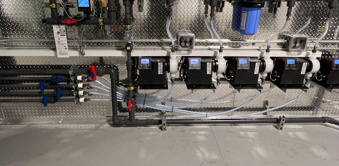
Connecting Nutrients. For skid mounted systems, the nutrient dosing pumps are located on the rear of the machine skid, mounted to brackets on three horizontal rows of four pumps each. The skid can accept up to twelve (12) dosing pumps. For Custom, wall-mounted units, the pumps will install on brackets mounted to the wall between the plumbing sections. Custom systems can accept up to ten (10) dosing pumps.
During configuration, each dosing pump will be assigned a specific nutrient, additive, or as pH Up/Down. Nutrient pumps will come pre-plumbed with ½” ID flexible tubing with a foot valve connected to the end. If utilizing drums or other similar containers for stock tanks, this tube and foot valve assembly simply need to be placed into the assigned container, with the foot valve sitting on the bottom of the container. If cone-bottom stock tanks are utilized, the foot valve will not be used and can be removed and the flexible pickup tubing will install directly into the hard-piped PVC plumbed from the bottom of the stock tank. This PVC plumbing should be minimum 1” PVC and should route from the bottom of the stock tank over to the skid and stop below the pumps. A ½” barb adapter fitting should be utilized at the end of the PVC run to attach the flexible tubing from the suction side of the dosing pump to the PVC pipe. In this case, a mesh strainer should be plumbed in line between the stock tank and dosing pump to prevent sediment from getting into the dosing pump. The nutrient tubing may need to be trimmed to fit properly. In such a case, remove the foot valve from the flexible tube. Trim the tube to the appropriate length. Push tubing back onto the foot valve and secure the hose-clamp. The proper length of the tubing should allow the foot valve/strainer to rest in a vertical position, just touching the bottom of the nutrient container. If a particular nutrient tends to settle, the strainer may need to be picked up off the bottom of the container to prevent sediment from clogging and loss of prime from occurring.
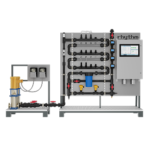
Example of nutrient placement for skid-based inline systems
Example of nutrient pumps connected to plumbing lines into stock tanks
Rhythm includes approximately 10ft of tubing per dosing pump. Replacement or supplementary tubing can be purchased at any home improvement store, plumbing supply stores, or online. Tube spec: Clear vinyl braided tubing in ½” I.D. / ¾”O.D.
Nutrient containers can be placed above, horizontal to, or below dosing pumps. Please note, the pumps are rated for 10ft of suction lift max. The Inline AFS should only be used with drip system friendly, liquid nutrients. Pre-mixed salts and powders are okay, as well are some organics, however fall-out from improper mixing or buildup from organics may cause functionality issues with the pumps. Contact your nutrient manufacturer to verify if your nutrient inputs are for use in drip irrigation systems. Failure to utilize a dosing friendly nutrient line may result in clogged injectors, dirty sensor probes, excessive build up in plumbing lines, and/or system failure.
The dosing pumps will require occasional cleaning, especially the Injection Fitting, the Foot valve/Strainer, and the pump head valves. The frequency will depend on the type and viscosity of the nutrient it is pumping, but we recommend cleaning once a month or whenever found to be clogged.
Clean the injection quill assembly. This is required especially when injecting fluids that calcify such as sodium hypochlorite. These lime deposits and other build ups can clog the fitting, increase the back pressure and interfere with the check valve operation. To clean the injection quill, remove the tubing from the quill by removing the union. Next, remove the injector quill from the plumbing by unthreading it from the plumbing tee. Rinse and flush with warm water and soap as necessary. H202 and any irrigation cleaner may also be used to remove build-up and residue, along with a soft bristle brush or pipe cleaner. After cleaning, reinstall into the Inline plumbing tee in the reverse order from which it was removed.
Injection quill assembly exploded view.
Clean the foot valve/strainer. Remove the foot valve and strainer attached to the tubing from the nutrient container and rinse with warm water. If it appears that a deeper clean is necessary, see Figure the image below on disassembly. Once disassembled, rinse all components with warm water and wipe away residue as necessary. Reassemble the foot valve/strainer and replace in nutrient container.
Video of foot valve / strainer assembly
Cleaning the dosing pump head. If a pump appears to struggle to dose a particular nutrient, it may need to be cleaned. First start by removing the pickup line from the nutrient. Clean the the foot valve/strainer assembly and replace with a new pickup tube. Place pickup in a container of warm, clean water and turn the pump on. Again, H202 or any irrigation cleaner may be added to the water to assist in removing and cleaning residue and buildup. Allow the pump to run clean water through it until it returns to normal operation. If the pump continues to remain clogged, the internal pump head will need to be cleaned. First, turn off power to the pump by turning off the breaker in the Main Inline AFS control cabinet. Rinse with warm water, or cleaner, using a soft-bristle brush as necessary until the components are clean. Reassemble and replace the head assembly. After the head assembly has been rinsed and wiped clean, it is a good idea to pump warm water repeatedly through the pump to remove any possible build-up that may remain.
Video of dosing pump head disassembly
Calibrating the Dosing Pumps
Keeping the Rhythm Batch Inline AFS dosing and sensing equipment calibrated will ensure accurate delivery of recipes and overall improve the performance of the machine. Regular calibration is required for nutrient dosing pumps and pH / EC sensors. These procedures require no tools, hand tighten only! Use of pliers or tools will cause damage to the nuts and threads and can cause leaks.
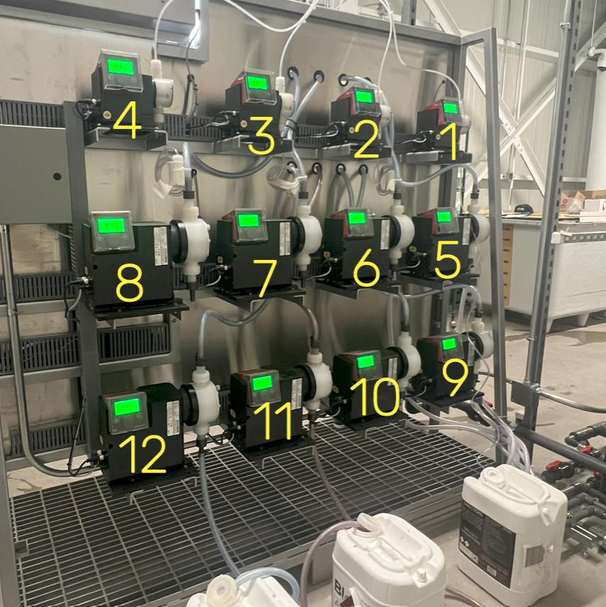
Dosing pump layouts. You can identify each dosing pump using the following diagram.
The nutrient injectors are situated from left to right on the backside (following the flow of inline water) starting at #1 and ending at max #12 (customer dependent). See the image above for the dosing pump numbering scheme. From top to bottom: First row is 4-1, second row is 8-5, and bottom row is 12-9.
Dosing pump calibration procedure. Calibrate the nutrient dosing pumps once every month, or if EC begins to stray from known recipes, this could be an indication a dosing pump needs to be recalibrated.
For a video on how to calibrate, please click the image below.
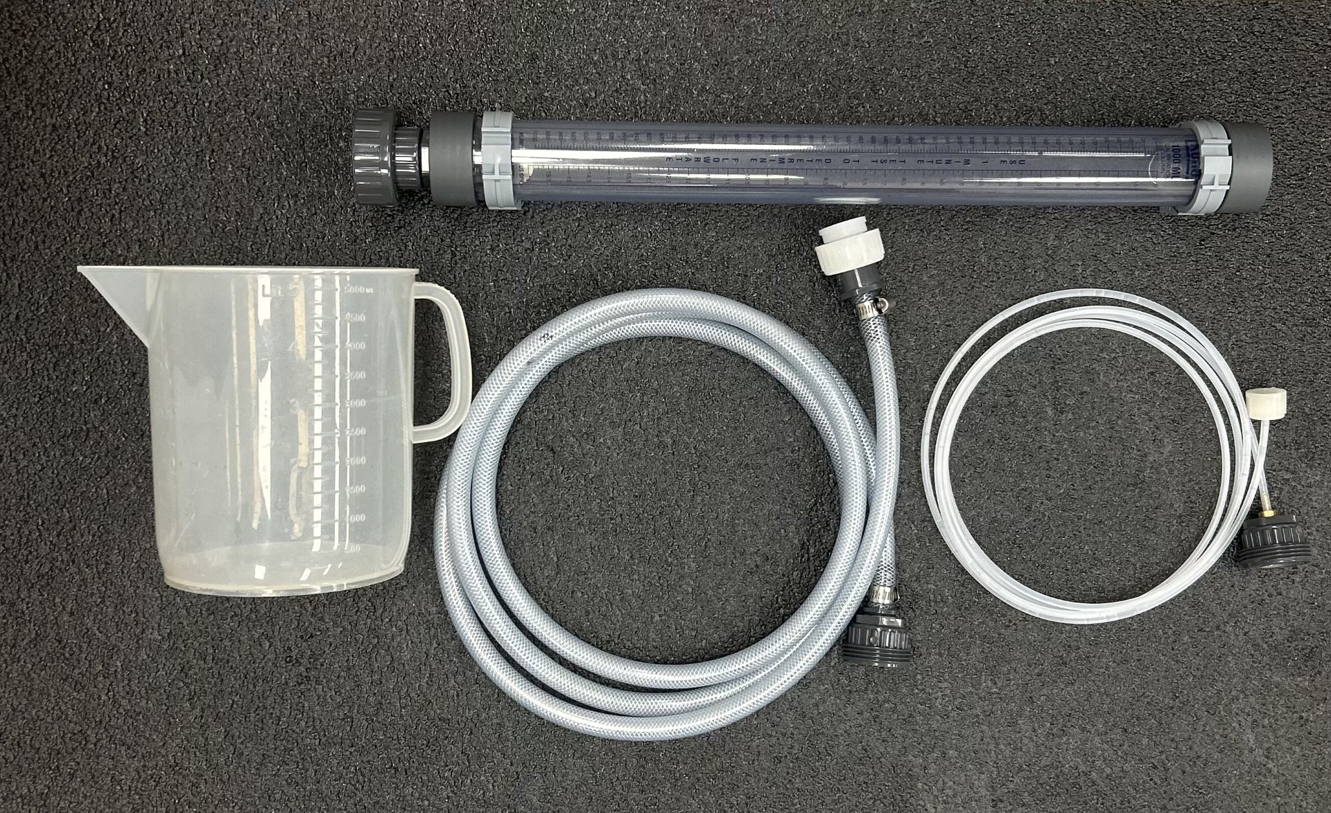
MATERIALS NEEDED: To calibrate each pump, you will need a measuring cup, the inline calibration column, 1/4" flex hose (for low dose pumps) and 1/2" flex hose (for high dose pumps).
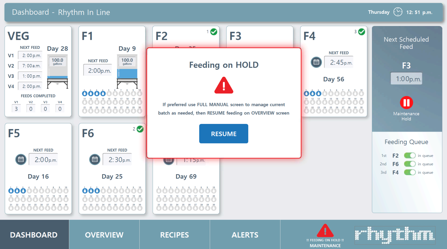
Step 1 • Place the machine on hold in the software. Do this by going to the Dashboard screen in your software and pressing the gray pause button labeled "Place all feeds on hold." Once on hold, button will turn red and a popup labeled "Feeding on HOLD" will appear.
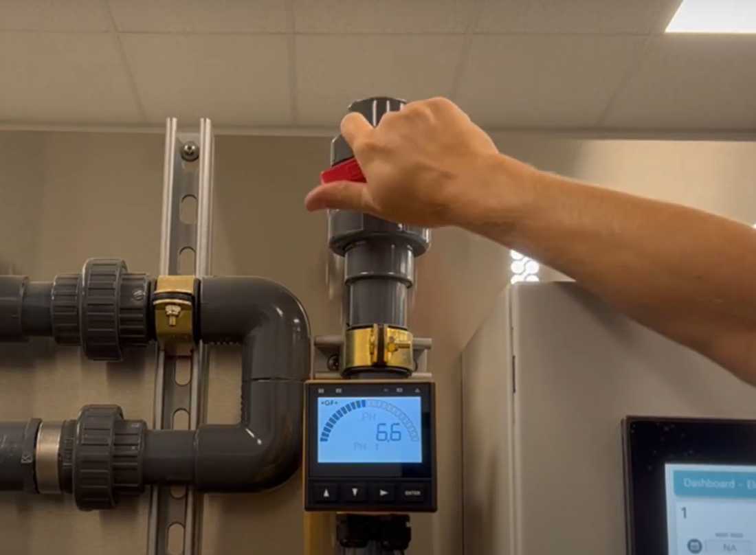
Step 2 • Close the outgoing water line valve located at the top of the ph & ec sensor manifold, to the left of the "Rhythm" logo and cabinet.
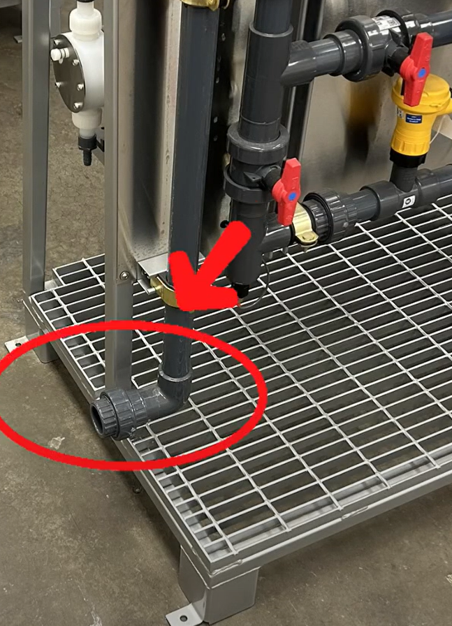
Also close the incoming water line ball valve located to the left lower side of the skid. This valve will vary in shape size and color as it is provided by your plumber.
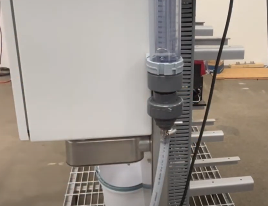
Step 3 • Open the hose bib to drain the system. Leave this open.
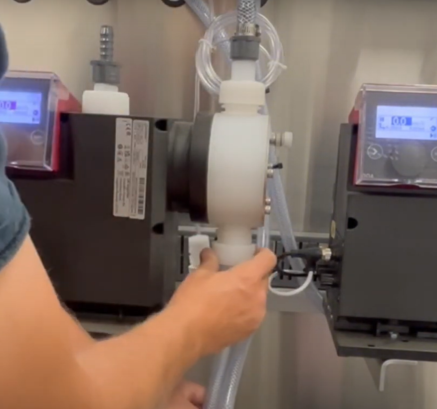
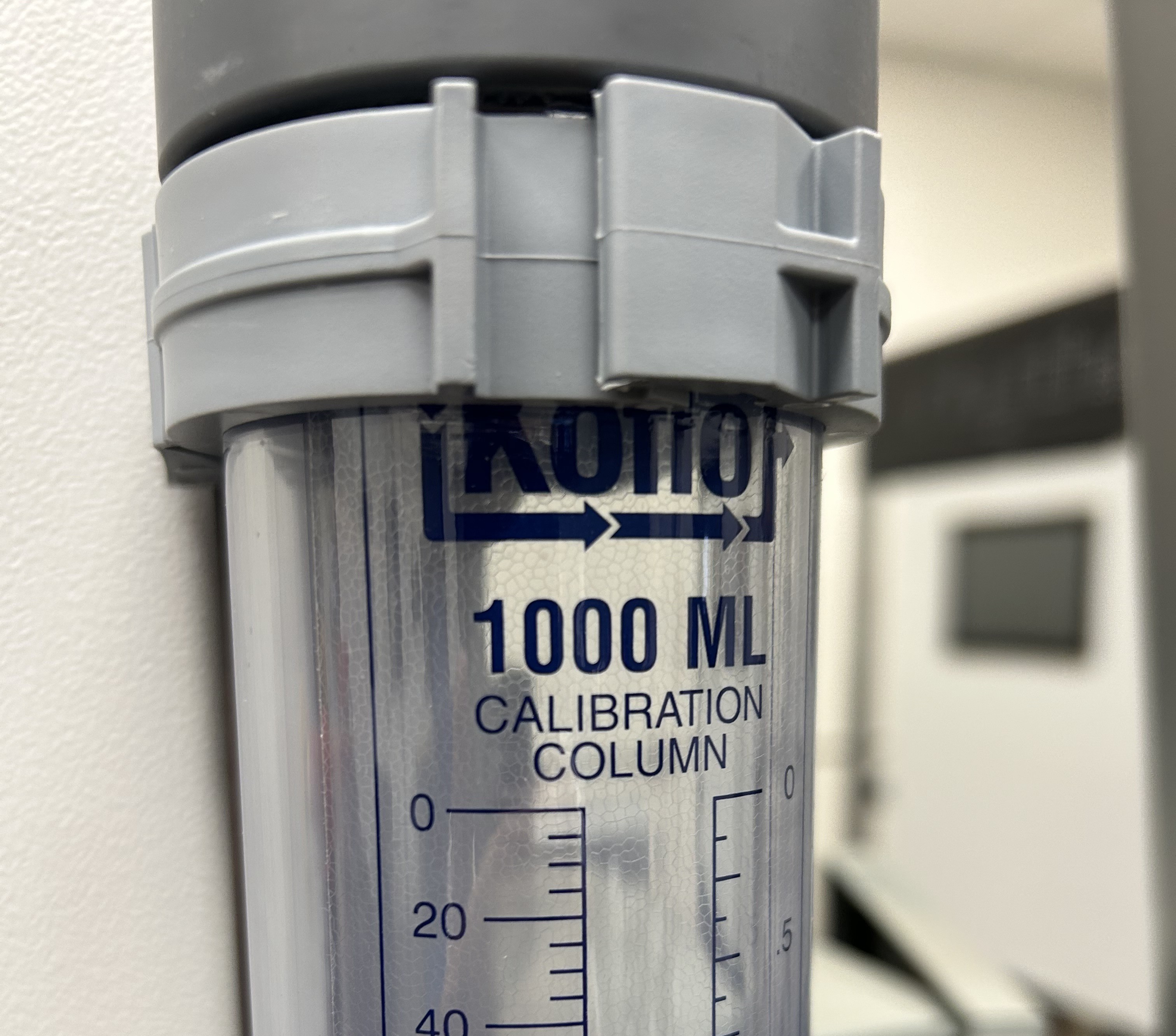
Step 4 • The inline calibration column is magnetic. Attach it anywhere on the skid, making sure it's level. Attach the flex tubing to the bottom of the column. Use the 1/2" larger tubing for the high dose pumps and the 1/4" thinner tubing for the low dose pumps.
Remove the suction tip on the front of the dosing pump and connect the other end of the flex hose.
Take your measuring cup and add water to the calibration column to prepare for priming the pump. The column measures 1000ml and you will want to fill it all the way to the top line "0"
Step 5 • Bleed the pump by slightly loosening the prime nut to release a bit of air. You can then press and HOLD the "100%" button on the dosing pump screen (lift the clear cover to access) to start priming. Once some water drips out, tighten and close the prime nut (while still HOLDING the 100% button). Keep holding until all air bubbles are released from the hose. This process should only take a couple of minutes.
Fill the calibration column back up with water to the top.
Step 6 • Go to the interface screen on the dosing pump (where you pressed 100%) and place the pump on hold by pressing the white > arrow. Make sure the STOP ⬛ is displayed in the upper left hand corner of the screen.
Use the center dial to scroll to the SETTINGS ⚙️icon and press down. The Setup menu will appear. Scroll down to CALIBRATION and press the dial.
Use the dial to navigate to START and press down on the dial. The screen will turn green and start counting. FOR HIGH DOSE PUMPS: We are trying to get the pump to 900ml so press STOP around the 70 strokes mark. FOR LOW DOSE PUMPS: Let the count run until it stops. Go back to the calibration column and record the mls of water inside. Go back to the dosing pump screen and scroll to "Calibration Volume" and enter the amount you just recorded by scrolling the knob. For example, "920ml". Press the dial down. Use the dial to navigate back to the HOME 🏠 icon and press the dial. Press the white arrow > button to go back into operation mode. Display should now show a PAUSE ▐▐ icon in the upper left.
Remove the flex tubing from the dosing pump, replace the suction tip and repeat the process for the next pump. Remember that smaller dosing pumps will use the thinner hose.
Ordering Replacements
Your Rhythm Inline Series AFS is equipped with many off-shelf parts and equipment, built for ease of repair or replacement. Additionally, your purchase comes with the following spare parts:
AFS spare parts kit
Qty – 2: 1" Netafim solenoid valve (if your system was ordered with a manifold) Qty – 5: Fuses
Replacing dosing pumps. If your pump is experiencing problems, please see the following section for Troubleshooting issues to see if the problem can be amended before considering a complete replacement. Sometimes, pumps will malfunction or be damaged by the user. In this case, contact Rhythm Support at 833-749-8461 or at support@rhythmcss.com to request support for replacing dosing pumps.
Troubleshooting
1. A dosing pump is not pumping a nutrient.
If you can hear the pump motor turn on, but nothing pumps out, follow these steps to diagnose the issue:
• Priming the low dose pump. The initial pickup may be jammed. Turn the pump to max power by adjusting the knob on the top of the pump to "9", then grab the dosing line feeding into the nutrient container and jiggle the foot valve with the ceramic weight and filter around in the container so it can clear out air bubbles and start suctioning again. • Clean the injection/check valve and foot valve/strainer. It is likely the injector or foot valve is clogged. Certain nutrients with high salt contents that tend to settle or stick to surfaces, can clog the internals of the injector. See Cleaning the foot valve section above for detailed instruction and pictures of how to disassemble and clean these components.
• If this does not fix the issue, the pump itself may be clogged and need to be cleaned. You can first start by running warm water through it repeatedly to flush out the internals. First begin by removing the nutrient it is attached to and removing the suction tube and outlet tube from the pump. Remove the injector/check valve and foot valve strainer from the dosing tubing and make up a new clean tube that you can route from a bucket of fresh water, to an empty bucket. Supplementary tubing can be purchased at any hardware store in size 1/4" ID (inner diameter) x 3/8" OD (outer diameter). Once the tubing is in place, fill a bucket of water with WARM, fresh, clean water and place the suction side of the tubing into this bucket. Place the outlet tubing with the injector nozzle over the empty bucket. Turn on the pump and allow it to pump all of the water from one bucket to the next. You should start to see sediment and residual build up being flushed from the pump. Continue until only clean water comes out of the output side.
• Finally, if this still isn’t solving the issue, the pump head will need to be removed, and internal components flushed and cleaned. See the Cleaning the dosing pump head section above for details.
Contact Rhythm CSS customer for additional assistance if cleaning does not solve the issue.
2. A nutrient is settling or separating while sitting in the tank and doesn’t pump evenly over time.
Shake the nutrient container daily to agitate the mixture if you have small 5-6 gallon jugs. If you have something larger, such as 55 gallon drums or 275 gallon totes, you may want to install a simple fountain pump into the nutrient container. A 400-600GPH pump on a timer set to come on in intervals is plenty to keep the solution mixed. Start with the minimal interval, the most common is 15 minutes, and set the timer to turn the fountain pump on for 15 minutes every 2 hours. Adjust this setting to find an ideal balance.
3. EC / PPMs are consistently coming in too low during recipe preparation.
Many times this results in the AFS stopping the recipe preparation process and alerting the user that it was unable to achieve the EC setpoint.
First and foremost, check all the nutrient inputs, starting with the bases, to ensure that they are adequately full, and the pickup tube and foot valve/strainer are properly resting in the bottom of the container. If one of the base nutrients is low, or for some reason the pickup tube was pulled out of the container, the recipe will be missing that nutrient and will not come in at the proper EC.
During stabilization, the process would attempt to add more of the bases to reach the desired EC setpoint and may or may not be able to achieve this. Many times, the AFS runs through the allowable cycle attempts to adjust EC before being able to achieve the setpoint. It then stops the process and notifies the user via email or text notifications. If it does achieve the EC setpoint of the recipe, but was missing one of the inputs, your recipe could look like it was correct by EC, but in fact would be out of balance. This actual situation occurred to a customer and unbeknownst to the grower, they were feeding only Base A, none of Base B, for an entire week before they noticed the pickup tube from the dosing pump had gotten pulled out of the Base B container. Be mindful of small changes in the way the AFS is preparing recipes, it could be the indicator something is not quite right.
4. There are air bubbles in my nutrient lines.
If you find air bubbles developing in your nutrient dosing line, the first step in troubleshooting the issue is to make sure the pump fittings are clean and no air is being pulled into the system. We do this by checking that all of your tubing connections to pump fittings are properly fitted and tight. Check the injector of the line with the air bubbles at the cross-bar, checking to make sure the tube is sitting all the way down over the nipple and the nut is tightly secured. At this time, you can also pull the injector off to clean it. Be careful to avoid any fittings or nuts that might fall into the tank when removing them. Also, check the connections to the pump, one to the top of the pump and one to the bottom, and finally the foot valve at the end of the nutrient suction line.
There is also a possibility that the foot valve is sucking in air when the nutrient solution is running low or the foot valve is not completely submerged. In this case, you can re-calibrate the dosing pumps or manually turn on the nutrient in the software to get past the bubbles (MANUAL MODE > Nutrient #).
If air bubbles continue to develop and you have verified all the fittings in the system are clean and are not allowing air in the line, it could be that the type of fluid being dosed allows air bubbles to get by the injector check valve.
We can also try replacing the pump altogether to see if the issue resolves. Contact us to get a replacement.


.svg)