Keeping the Rhythm Batch Series AFS dosing and sensing equipment calibrated will ensure accurate delivery of recipes, increase mix times, and overall improve the performance of the machine. Regular calibration is required for nutrient dosing pumps and pH / EC sensors. These procedures require no tools, hand tighten only! Use of pliers or tools will cause damage to the nuts and threads and can cause leaks.
Many times, simply keeping the sensors clean will prohibit build-up and the need for weekly calibrations. Clean the pH and EC probes by running warm water repeatedly over the electrode. A soft brush may be used to remove build up on the surface of the electrode. Be very careful not to break the glass end on the pH electrode. A pipe cleaner may be used to clean down into the spaces of the EC electrode.
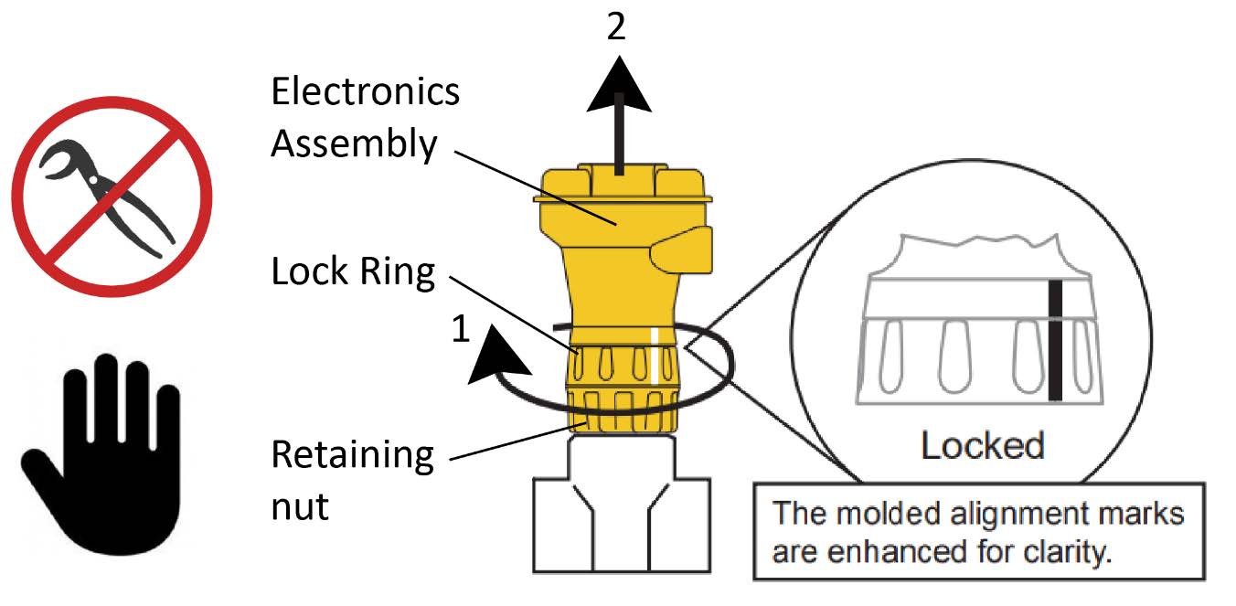
See the images below for a visual representation of removing pH and EC electrodes from the plumbing line:

Removing the pH sensor probe for calibration: To remove the pH electrode assembly, hold the lock ring in place, unthread the retaining nut and carefully pull the entire assembly and probe straight out from the plumbing tee.
Removing the EC probe for calibration: To remove the EC electrode, unscrew the black nut at the end of the electrode and pull the electrode straight out from the plumbing tee. Do not use pliers or wrenches as they can damage the threads.
You can watch the video below for more guidance on cleaning and calibrating the probes.
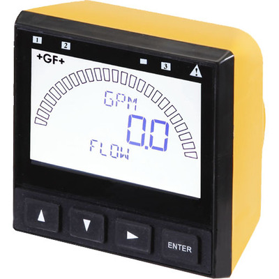
Your new Signet 9900 Transmitter needs to be calibrated and the sensor needs to be initialized prior to use. The following steps outline the recommended procedure to start up a new system. The GF Signet sensor/transmitter
full instruction manual can be found by clicking here, but the following is a quick list for required setup items:
Unit password is ▲▲▲▼ (up up up down).
To move BACK to previous screen, press ▲▼simultaneously.
Set up the Type of probe attached. When the 9900 is first powered on, it will attempt to determine the sensor type connected when ENTER is pressed (unit will display LOOKING FOR). If no sensor is attached to the 9900, the words “TYPE” and “FLOW” are displayed. If the 9900 does not identify your sensor type correctly, use the ▲ and▼ keys to select your sensor type. For pH probes, select "PH" and for EC probe, select "COND/RES." As you scroll through the available sensor types, press ► to select the desired sensor and then press ENTER.
Change the Name of your sensor (pH and EC). Hold ENTER for 3 seconds to get into menu. Use ► to navigate to INPUT and press ENTER. Use ▲▼ to navigate to NAME and press ►. Enter ▲▲▲▼ (UP UP UP DOWN) password. Use ▲▼ ► to enter “EC1" for TOP EC sensor, or "PH1” for TOP PH sensor and “EC2" for second EC sensor, or "PH2” for second PH sensor respectively (center the text on the screen). Press ENTER to SAVE.
Change the Temperature scale of your sensor (pH and EC). Hold ENTER for 3 seconds to get into menu. Use ► to navigate to INPUT. Navigate to TEMP UNITS and set to Fahrenheit.
Change the Cell Constant (EC only). Hold ENTER for 3 seconds to get into menu. Press ▲▼ arrows to navigate to CELL CONSTANT. Cell Constant Value is printed on the brown sensor cable. The value is displayed as “K =x.x”. Ensure the CELL CONSTANT value matches the “K” value printed on the sensor cable. Press ENTER to save.
Set the Scaling (EC only). From main menu navigate to LOOP and press ENTER. Press ▲▼ until you reach “L1 20mA SETPT”. Factory setting is 100. Use ▲▼ ► arrows to change this value to 10.
Set the Bar Max (EC only). From main menu navigate to OPTION and press ENTER. Use ▲▼ arrows to navigate to “SET BAR MAX” and set this value to 10.
How to change the unit of measure on the sensor (EC only). The factory unit of measure is EC, or mS. To change, hold ENTER for 3 seconds to enter the MENU. Navigate to INPUT MENU and press ENTER. Navigate to COND UNITS and press RIGHT ARROW. Select between μS, mS, PPM, KOhm, or MOhm. IF the COND UNITS is set to PPM, set the ratio of Total Dissolved Solids to μS. Default = .50.
Change the Input (pH only). Hold ENTER for 3 seconds to get into menu. Use ► to navigate to INPUT and press ENTER. Navigate to CHANNEL TWO and set to “TEMPERATURE."
How to factory reset a sensor. If replacing the pH electrode with a brand new one, it is recommended to RESET the sensor to factory calibration. To RESET, in the CAL MENU, navigate to RESET PH CAL and press RIGHT ARROW.
Troubleshooting error messages. Please see the
GF Troubleshooting Guide for common issues and error messages.
Nutrients will leave residual deposits on the surfaces of the pH probes, potentially causing inaccurate readings. The level and speed to which this build up occurs will depend on the type of nutrients used, frequency of use, and EC levels of feed batches. Monitoring flow, pressure and water conditions will guide your maintenance schedule, but we recommend calibrating the pH sensors once a week for optimal performance. Each sensor has a probe mounted in a plumbing tee to the rear of the yellow and black display unit, in the vertical section of pipe. The probes require removal from the plumbing tee for calibration which can be done by hand with tool-less removal. You will leave all electronics plugged in during the calibration procedures. Be careful handling all equipment as dropped equipment or probes will likely cause damage.
Step 1 • Drain the system. The first step before calibration is to drain the vertical plumbing and manifold prior to removing electrodes from the plumbing system. Make sure the machine is not mixing any batches currently or any time soon. To avoid action during your calibration process, simply go to Rhythm Logo > FULL MANUAL to activate full manual which will pause all processes. To release pressure, in FULL MANUAL,
open the agitation solenoid and slowly open hose bib, using a bucket to catch water.
Step 2 • Remove the pH probe. Hold the lock ring in place, unthread the retaining nut and carefully pull the entire assembly and probe straight out from the plumbing tee. This process may also relieve some air from the lines so make sure to keep the bucket below the hose bib.
Step 3 • Prepare the buffer solutions. Calibrating the pH sensor requires prepared 4.0, 7.0, or 10 pH buffer solutions (any two). The solutions can be used to calibrate more than one sensor; however, the solution must remain free of debris and must not be diluted by rinse water from previous calibrations.
Step 4 • Clean the probe. Before beginning, if the probe requires cleaning, rinse repeatedly with warm water. A soft bristled brush may be used to GENTLY clean the surface of the probe. Be careful not to allow the glass end to touch any hard surfaces as it could break.
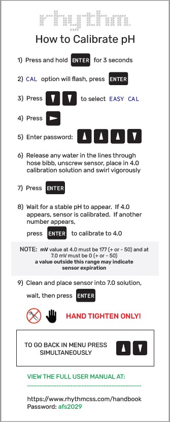
Step 5 • Calibrate the sensor. Place the probe inside the 4.0 solution, making sure the tip of the probe does not touch the bottom of the cup. Follow the steps on the calibration card to calibrate the probe for the 4.0 solution and the 7.0 solution. Click on the image below to get a PDF file of the calibration card:
Nutrients will leave residual deposits on the surfaces of the EC probes, potentially causing inaccurate readings. The level and speed to which this build up occurs will depend on the type of nutrients used, frequency of use, and EC levels of feed batches. Monitoring flow, pressure and water conditions will guide your maintenance schedule, but we recommend calibrating the EC sensors once a week for optimal performance. Each sensor has a probe mounted in a plumbing tee to the rear of the yellow and black display unit, in the vertical section of pipe. The probes require removal from the plumbing tee for calibration which can be done by hand with tool-less removal. You will leave all electronics plugged in during the calibration procedures. Be careful handling all equipment as dropped equipment or probes will likely cause damage.
Step 1 • Drain the system. The first step before calibration is to drain the vertical plumbing and manifold prior to removing electrodes from the plumbing system. Make sure the machine is not mixing any batches currently or any time soon. To avoid action during your calibration process, simply go to Rhythm Logo > FULL MANUAL to activate full manual which will pause all processes. To release pressure, in FULL MANUAL,
open the agitation solenoid and slowly open hose bib, using a bucket to catch water.
Step 2 • Remove the EC probe. Hold the lock ring in place, unthread the retaining nut and carefully pull the entire assembly and probe straight out from the plumbing tee. This process will also relieve some air from the lines so make sure to keep the bucket below the hose bib.
Step 3 • Prepare the buffer solution. The EC calibration procedure will only utilize the MANUAL CAL procedure option. The AUTOCAL will not be used. Any standard buffer solution may be used in MANUAL CAL but we recommend using something in your typical feed range. BlueLab’s 2.77EC Conductivity Solution is a good choice. The solution can be used to calibrate more than one sensor; however, the solution must remain free of debris and must not be diluted by rinse water from previous calibrations.
Step 4 • Clean the probe. Before beginning, if the probe requires cleaning, rinse repeatedly with warm water. A soft bristled brush may be used to GENTLY clean the surface of the probe. Be careful not to allow the glass end to touch any hard surfaces as it could break.
Step 5 • Calibrate the sensor. Place the probe inside the 2.77 EC solution, making sure the tip of the probe does not touch the bottom of the cup. Follow the steps on the calibration card to calibrate the probe. Click on the image below to get a PDF file of the calibration card:
Your Rhythm Batch Series AFS is equipped with many off-shelf parts and equipment, built for ease of repair or replacement. Additionally, your purchase comes with the following spare parts:
AFS spare parts kitQty – 1: pH probe (covered under warranty but not shipped with initial system due to expiration.)
Qty – 2: 1" Netafim solenoid valve
Qty – 5: Fuses
Replacing pH probes. If your pH sensor is experiencing problems, please see the following section for
Troubleshooting issues to see if the problem can be amended before considering a complete replacement. pH probes will usually need to be replaced yearly. Your first pH probe is covered under warranty, but each subsequent probe will be charged at the current market price. To get your probe replacement, contact Rhythm Support at 833-749-8461 (text or call) or at
candice@rhythmcss.com to request support for replacing pH probes.
Replacing EC probes. If your EC sensor is experiencing problems, please see the following section for
Troubleshooting issues to see if the problem can be amended before considering a complete replacement. EC probes should not need to be replaced unless they dry out and become defective. For support on a problematic EC sensor, please contact Rhythm Support at 833-749-8461 (text or call) or at
candice@rhythmcss.com.
Make sure the probe is properly connected to the transmitter module. Reconnect and ensure the “twist-lock” connection is fully seated.
This is an indicator that the sensor needs to be recalibrated and/or the system plumbing needs to be flushed. If it has been a while since the last cleaning, do that now. After cleaning the sensor probe, reinstall and see if that corrected the issue. If not, move forward with recalibrating both sensors. Try to gather data by testing the same solution with a different probe (i.e BlueLab pH probe). If the reading is still significantly off, and you've done all the testing and trust the calibration procedures, the electrode may be bad. Contact Rhythm for support on replacement by calling or texting 833-749-8461.


.svg)